ESAB Cutting Systems
CROSSBOW Page 46
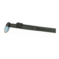
3.3 Oxy-fuel Torch Installation
If the optional Oxy-Fuel torch was purchased, it must be assembled and installed into the torch holder.
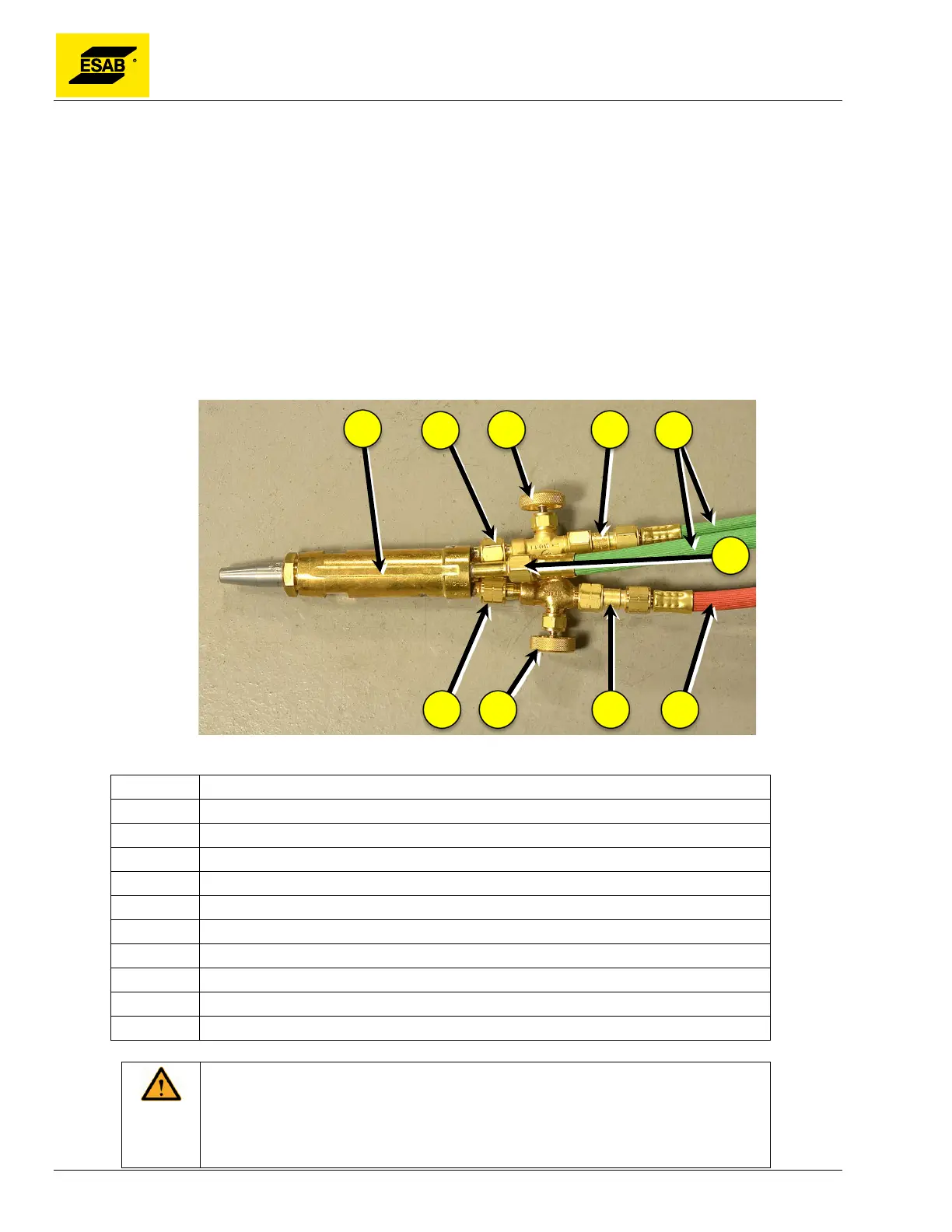
3.3.1 Assemble Torch
Assemble torch, needle valves, check valves, and torch hoses. Assemble the needle valves to the inlet
fittings on the top of the torch, as shown. Assemble check valves to the needle valves. Connect hoses
as shown.
Note: the flow direction will be opposite of that shown on the needle valves, which is perfectly
acceptable in this application.
Figure 24: Oxy-Fuel Torch Assembly
Number Description
1 Oxy-Fuel Torch, Part Number 28X47 (C-69) or 28X53 (C-70)
2 Preheat Oxygen Inlet
3 Needle Valve, Part Numbers 3395 (Oxygen)
4 Check Valve, Part Numbers 639110 (Oxygen)
5 Oxygen Gas Supply Hoses, Part Number 0560951218
6 Cutting Oxygen Inlet
7 Fuel Gas Supply Hose, Part Number 0560951216
8 Check Valve, Part Number 0560985522 (Fuel Gas)
9 Needle Valve, Part Numbers 3396 (Fuel Gas)
10 Fuel Gas Inlet
The oxygen valve, fittings, and hoses have all been thoroughly cleaned for
oxygen service to remove combustible hydrocarbons. Keep all oxygen hoses
and fittings clean during installation. Cap-off unused fittings to keep clean
until used.