ESAB Cutting Systems
CROSSBOW Page 167
6) Remove and replace the V-Wheel, ball bearings, or other components from the V-Wheel
Shafts as necessary.
7) Clean and lubricate V-Wheel Shaft.
8) Reassemble in reverse order.
9) Adjust V-Wheel Tension per the above procedure.
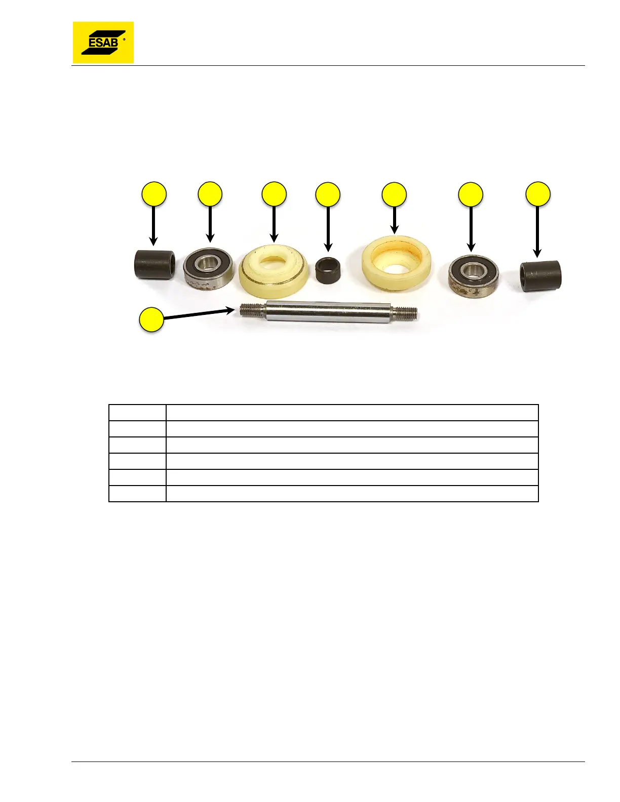
Figure 133: V-Wheel Assembly
Number Description
1 Centering Spacer Sleeve
2 Ball Bearing
3 V-Wheel
4 V-Wheel Spacer
5 V-Wheel Shaft