208 Upgrade and Maintenance Manual TX1320 M4
10.1 Basic information
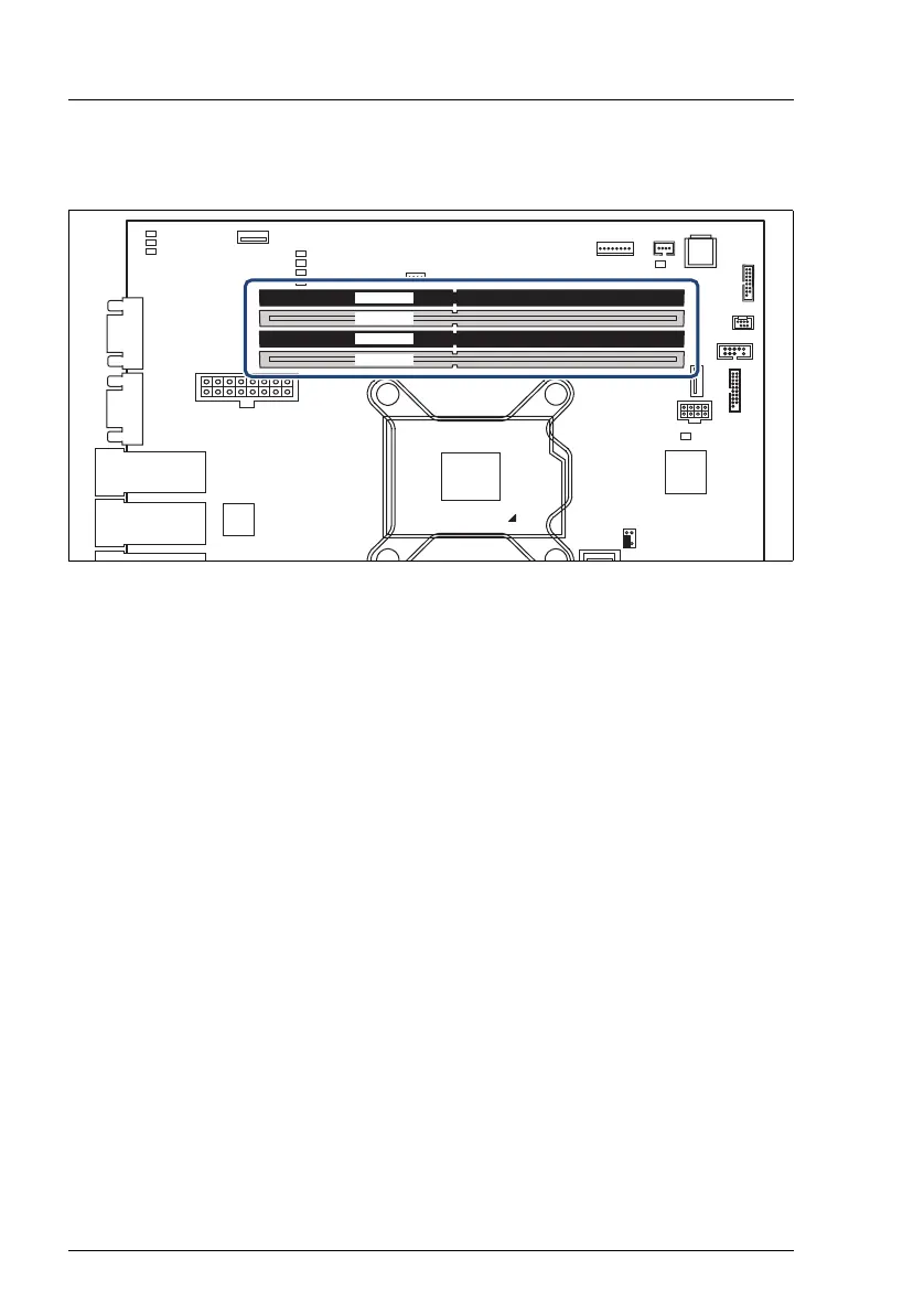
Figure 112: Slots of the main memory
The system board is equipped with 4 memory connectors
The system has to be equipped with at least one memory module.
10.1.1 Memory sequence
10.1.1.1 Population rules
– Populate memory slot 1 / channel A (DIMM 1A) first.
– Within all channels memory slot 1 must be populated prior to slot 2.
– For maximum performance, populate both channels with the same amount
of memory (symmetric dual channel configuration).
– If memory modules with different capacities are used:
– Install modules with higher capacities first.
– Within a channel, install modules in descending order of capacity.
– If memory modules with different speeds are used, the lowest clock rate
applies for all DIMMs.
CPU
RCVR
PWD CLR
12
nal connectors
LAN 1
Management
LAN / USB 2.0
LAN 2 /
VGA
Shared LAN 1 /
USB 2.0
Serial
Micro
SD
Frontpanel
OOB
USB 2
PWR1
Front USB
USB 1
ROC
FAN4
P30
PC98
PWR MAIN
iRMC
S5
Intel
i210
DIMM1B
DIMM2B
DIMM1A
DIMM2A
DIMM1A
DIMM1B
DIMM2B
DIMM2A

 Loading...