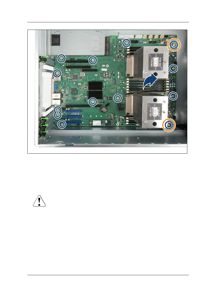
Figure 336: Removing the system board
▶
Remove the 13 screws (see blue circles, orange circles show the centering
bolts) from the system board.
▶
Use both hands to lift the system board carefully out of the chassis in a
slight angle. Thereby you pull the connectors out of the I/O panel.
CAUTION
▶
Always take the system board with both hands!
▶
Never lift the system board one-sided or at a heat sink,
because the solder connections between the socket and the
system board come under tension and increase the risk of
damage and malfunction!
▶
Do not damage the EMI springs which are essential to comply
with applicable EMC regulations and satisfy cooling
requirements and fire protection measures.
▶
Place the removed and the new system board on an antistatic surface.
System board and components
TX2550 M5 Upgrade and Maintenance Manual 517

 Loading...