9.3.6.3 RS-422
• There is the need to provide a termination resistor at either end of a transmission line.
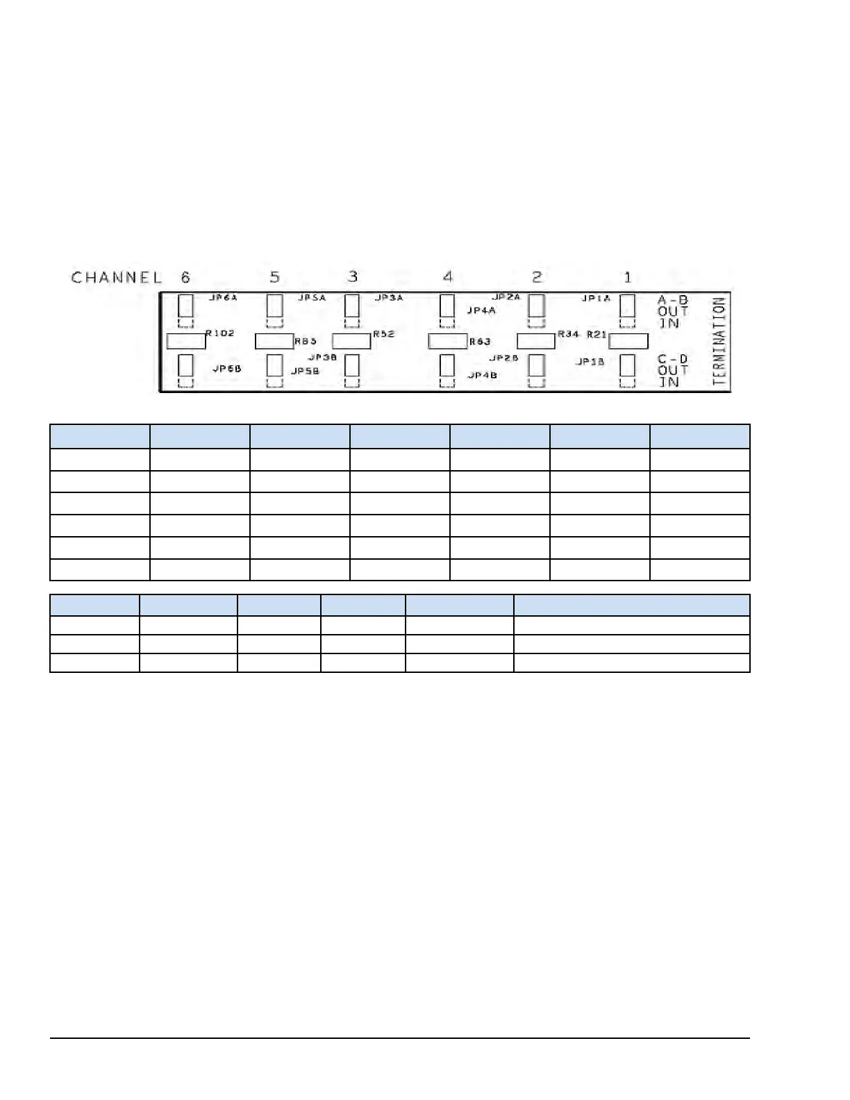
• SSCA provides selectable termination resistors for each pair of signal lines.
• Jumpers JP#A and JP#B apply or remove the termination resistors between signals A-B and C-D.
• Above Point 3 function is repeated for each serial communication channel. The default jumper position is to disconnect
the termination resistor.
• The SSCA is clearly marked to display the relationship of the termination jumpers and the serial communication channel
signals.
The configuration at SSCA jumper (JP#A, JP#B set to IN) must match the ToolboxST configuration as displayed in the
following diagram. The 120 Ω resistance selection is used as an example.
Terminal Board Screw Connections
Channel SCOM
A B
C
D RET
Channel 1 26 28 30 32 34 36
Channel 2 25 27 29 31 33 35
Channel 3 13 15 17 19 21 23
Channel 4 14 16 18 20 22 24
Channel 5 02 04 06 08 10 12
Channel 6 01 03 05 07 09 11
Protocol A B
C
D
Cable Length
RS-422 TX+ TX- RX+ RX- Up to 305 m (1000 ft)
RS-485 TX/RX+ TX/RX- Jumper from A Jumper from B Up to 305 m (1000 ft)
RS-232C DTR/RTS TX CTS RX Up to 15 m (50 ft) or 2500 pF
298 GEH-6855_Vol_II GEH-6855_Vol_II Mark VIeS Functional Safety Systems Volume II
Public Information
 Loading...
