8.6 Variable Function (Setting the Waveform Display Freely)
136
Description When setting combined use of the Scaling and Variable functions
When Auto-Correction of the Variable function is enabled (On, default set-
ting) ( p.257)
The Variable function settings change according to Scaling and vertical axis
(voltage axis) range settings. Set Scaling before setting the Variable function.
If you change Scaling settings after enabling the Variable function, the Variable
setting voltage is automatically corrected so that the displayed size of waveforms
is unchanged.
When Auto-Correction of the Variable function is disabled (Off)
Set the Variable function after setting Scaling.
If setting the Variable function first, enter post-scaling values (converted physical
values).
To display the full span of output from a sensor
By using the Scaling function in combination, voltage from a sensor can be con-
verted to the physical units of the measurement object.
Example:
Set Scaling as follows:
Scaling: Decimal or exponent, Two-Point Setting
Units: A
Sensor Output (Input 1): 1.23 [V]
→(Scale 1): 0 [A]
Sensor Output (Input 2): 5.78 [V]
→(Scale 2):10 [A]
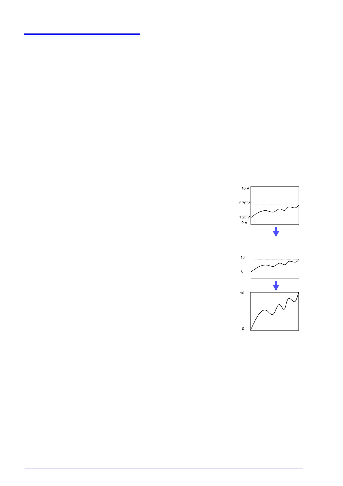
(with Variable function Off)
Voltage from the sensor is displayed as voltage.
It is displayed with the vertical axis (voltage axis) range
and at the zero position set on the Channel settings win-
dow (
[Analog] sheet).
The Variable function is set as follows:
Variable: On, Set Upper/Lower Limits
Lower Limit: 0 [A] Upper Limit: 10 [A]
The full span of output from the sensor is displayed.
 Loading...
