13.9 FFT Analysis Modes
245
13
Chapter 13 FFT Function
Waveform Example
Impulse Response
The transfer characteristic of a system is obtained as a time-domain waveform.
Utilizing both output and input signals of the measurement system, a unit impulse is applied to the
system and the corresponding response waveform is obtained.
Main uses:
To inspect circuit time constants
See: About the Functions"13.9.2 Analysis Mode Functions" ( p.254), "Linear Time-Invariant Systems"( p.A16)
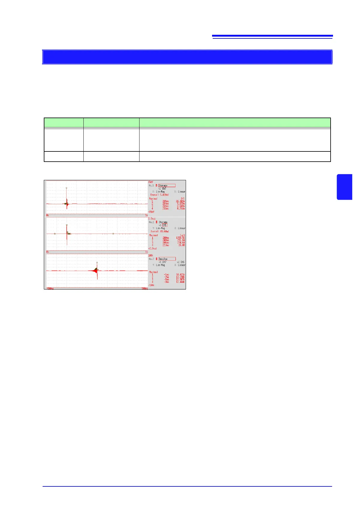
Axis Display Type Description
X axis Linear
Time display
The center (t = 0) is the reference. To the right is lag time (+t), and to the left is
lead time (-t)
Y axis Lin-Mag
This value is the transfer function provided by inverse Fourier transformation.
Normal display
X axis: Linear
Y axis: Lin-Mag
Input signal 1
Input signal 2
Impulse response