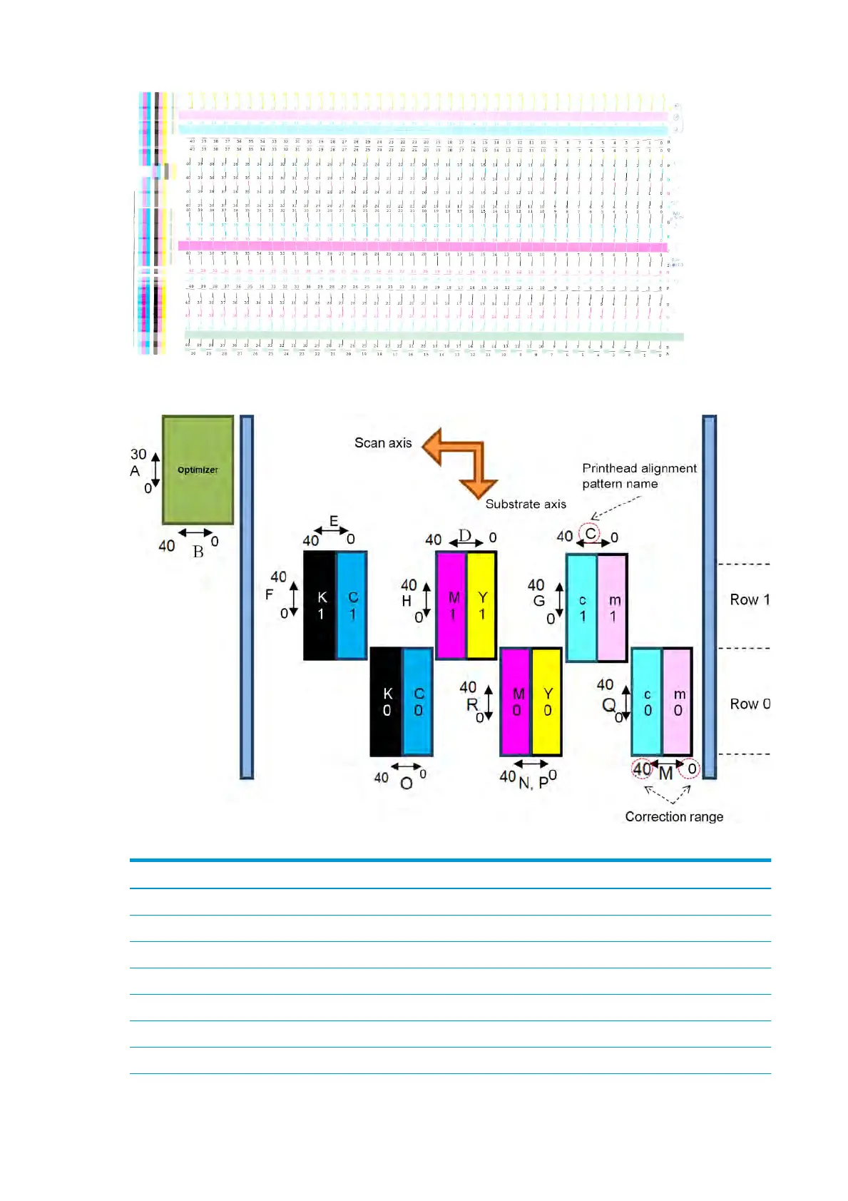
The picture below shows the distribution of printheads in the carriage. It also shows the correspondence
bet
ween printhead and patterns, with guidance on the direction of the corrections (0–40) applied.
The following table summarizes the correction type controlled by each pattern.
Pattern Aected
printheads Correction type
A Optimizer Substrate axis
B Optimizer Scan axis
C c1, m1 Scan axis
D M1, Y1 Scan axis
E K1, C1 Scan axis
F K1, C1 Substrate axis
G c1, m1 Substrate axis
138 Chapter 6 Printer calibration ENWW
 Loading...
