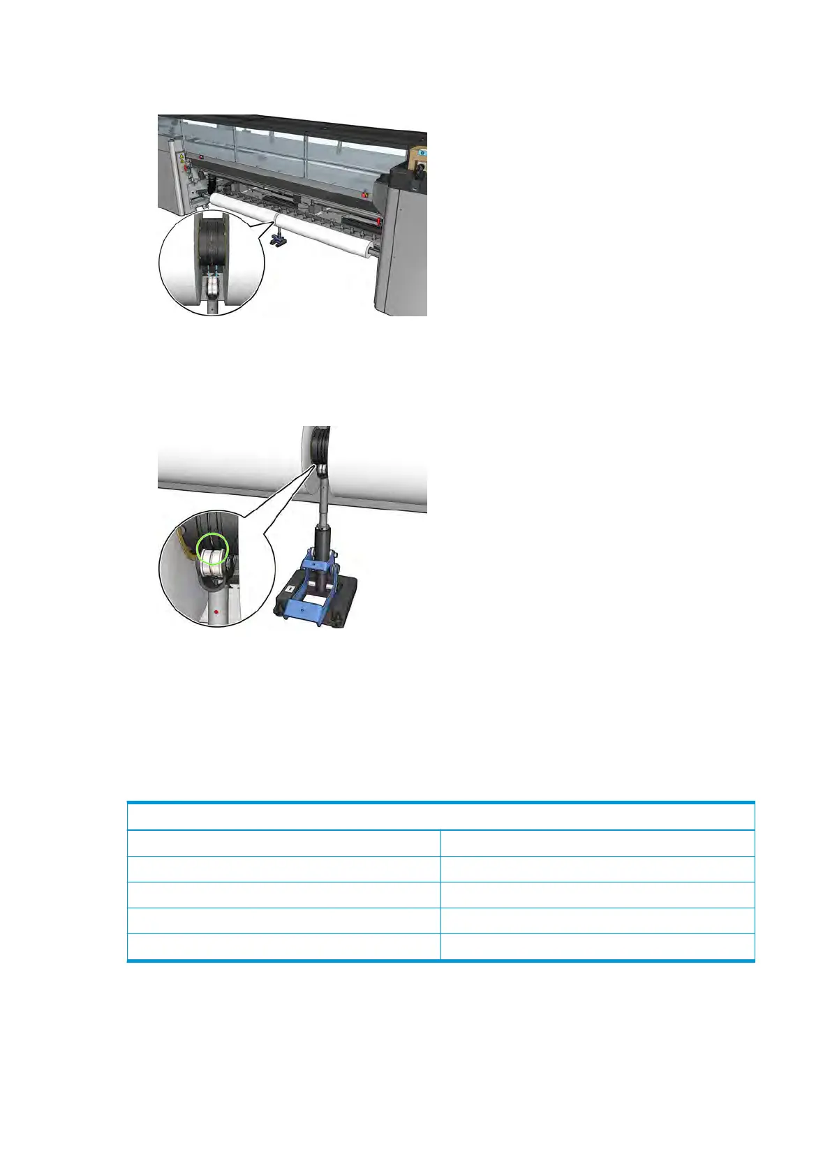
7. Position the dual-roll center support under the center of the dual-roll spindle.
8. Pul
l the long lever down.
When engaging the support, make sure that the position of the support bearings corresponds to the
grooves of the dierential cover and that the two sets of bearings are approximately the same distance
from the middle of the spindle to maximize their contact.
9. R
epeat the procedure for the output dual-roll spindle.
10. You can now feed the substrates into the printer.
11. Once the substrate is aligned, automatic substrate-edge detection can be run. If this automatic process
fails, or if you are using a roll width not within the dual-roll spindle specications shown below,
introduce the substrate edge values manually. Physically measure the position of the substrate edges
on the dual-roll spindle ruler. The dual-roll spindle ruler, in inches and centimeters, uses positive (+)
signs on one side and negative (−) signs on the other side.
Latex 3000/3100 dual-roll spindle specications
Minimum roll width 635 mm (25 in)
Maximum roll width 2 × 1.60 m (2 × 63 in)
Minimum gap between rolls 40 mm (1.6 in)
Maximum roll diameter 300 mm (11.8 in)
Maximum total weight of both rolls 2 × 70 kg (2 × 154 lb)
If this is the
rst time you use the dual roll, it has to be installed and calibrated:
50 Chapter 3 Handle the substrate ENWW
 Loading...
