244
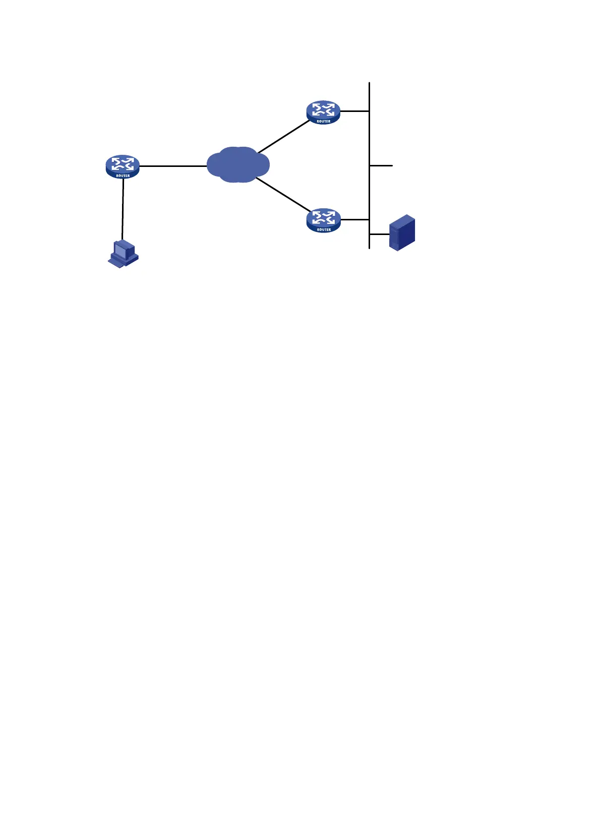
Figure 83 Network diagram
Configuration procedures
1. Configure Router A:
# Configure interfaces on Router A to make sure that the local DLSw peer 1.1.1.1 and remote
peers 2.2.2.2 and 3.3.3.3 can reach each other. (Details not shown.)
# Configure DLSw on Router A.
<RouterA> system-view
[RouterA] dlsw local 1.1.1.1
[RouterA] dlsw remote 2.2.2.2
[RouterA] dlsw remote 3.3.3.3
[RouterA] interface serial 2/0
[RouterA-Serial2/0] link-protocol sdlc
[RouterA-Serial2/0] baudrate 9600
[RouterA-Serial2/0] code nrzi
[RouterA-Serial2/0] sdlc status primary
[RouterA-Serial2/0] sdlc mac-map local 0000-2222-0000
[RouterA-Serial2/0] sdlc controller c1
[RouterA-Serial2/0] sdlc mac-map remote 0014-cc00-54af c1
[RouterA-Serial2/0] sdlc enable dlsw
2. Configure Router B:
# Configure interfaces on Router B to make sure that the local DLSw peer 2.2.2.2 and remote
peer 1.1.1.1 can reach each other. (Details not shown.)
# Configure DLSw on Router B.
<RouterB> system-view
[RouterB] dlsw local 2.2.2.2
[RouterB] dlsw remote 1.1.1.1
# Enable DLSw Ethernet redundancy on interface Ethernet 1/0, and configure the multicast
address as 9999-9999-9999 and set the priority to 10 for primary/secondary router election.
[RouterB] interface ethernet 1/0
[RouterB-Ethernet1/0] dlsw ethernet-backup enable 9999-9999-9999 priority 10
3. Configure Router C:
Internet
Router A
Router B
S2/0
Eth1/0
1.1.1.1/24
2.2.2.2/24
SDLC
LAN
LLC2
Host (SNA)
IBM AS/400
Router C
3.3.3.3/24
Eth1/0
 Loading...


