345
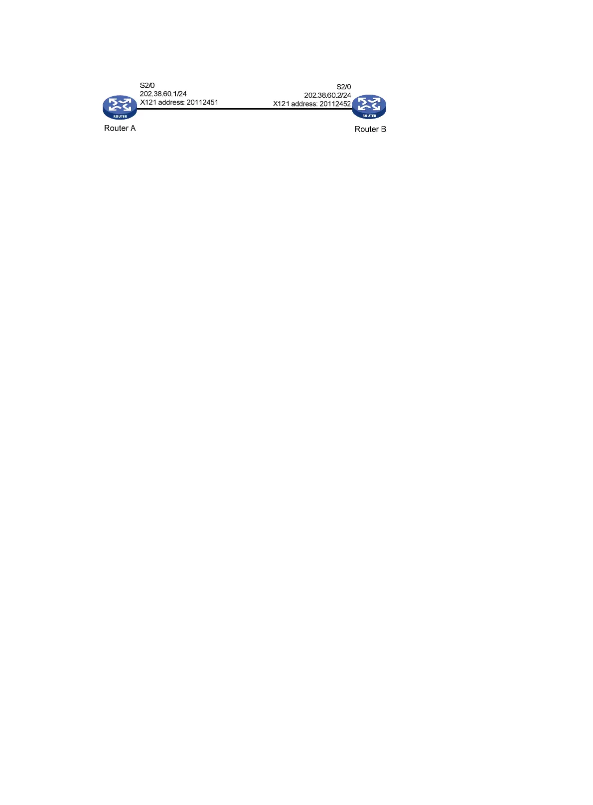
Figure 136 Network diagram
Configuration procedure
1. Configure Router A:
# Enter interface view.
<RouterA> system-view
[RouterA] interface serial 2/0
# Assign an IP address for the interface.
[RouterA-Serial2/0] ip address 202.38.60.1 255.255.255.0
# Configure the link layer protocol of the interface as X.25, and configure the interface to
operate in DTE mode.
[RouterA-Serial2/0] link-protocol x25 dte
# Assign an X.121 address to the interface.
[RouterA-Serial2/0] x25 x121-address 20112451
# Configure the address mapping to the peer.
[RouterA-Serial2/0] x25 map ip 202.38.60.2 x121-address 20112452
# Configure the maximum packet size allowed and the window size.
[RouterA-Serial2/0] x25 packet-size 1024 1024
[RouterA-Serial2/0] x25 window-size 5 5
[RouterA-Serial2/0] shutdown
[RouterA-Serial2/0] undo shutdown
2. Configure Router B:
# Enter interface view.
<RouterB> system-view
[RouterB] interface serial 2/0
# Assign an IP address to the interface.
[RouterB-Serial2/0] ip address 202.38.60.2 255.255.255.0
# Configure the link layer protocol of the interface as X.25, and specify it to operate in DCE
mode.
[RouterB-Serial2/0] link-protocol x25 dce
#Assign an X.121 address for the interface.
[RouterB-Serial2/0] x25 x121-address 20112452
# Configure address mapping to the peer.
[RouterB-Serial2/0] x25 map ip 202.38.60.1 x121-address 20112451
# Configure the maximum packet size allowed and the window size.
[RouterB-Serial2/0] x25 packet-size 1024 1024
[RouterB-Serial2/0] x25 window-size 5 5
[RouterB-Serial2/0] shutdown
[RouterB-Serial2/0] undo shutdown
Because the IP to X.121 mapping is available, IP addresses of both ends can be on different
network segments and no static route is needed.

 Loading...


