363
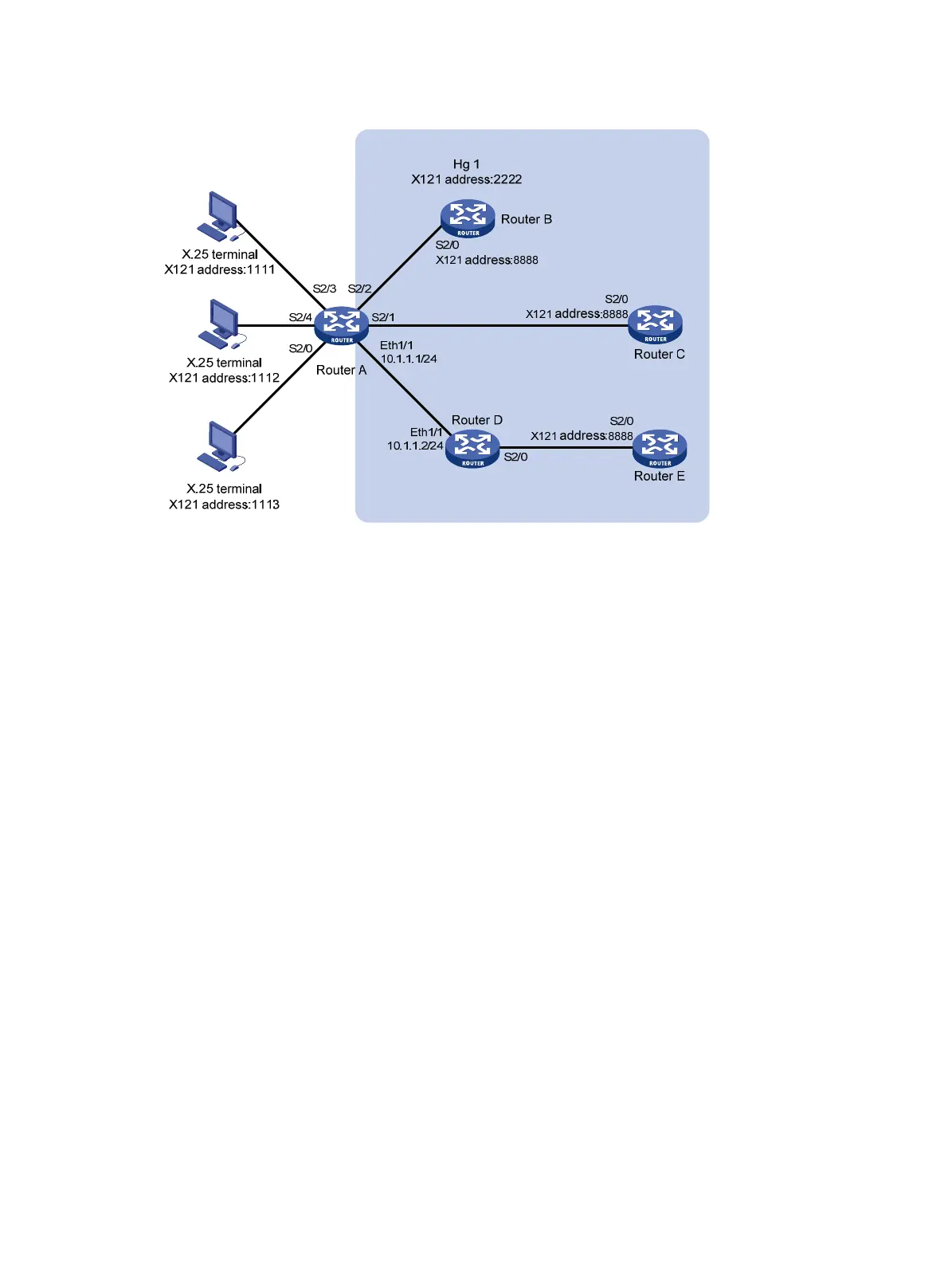
Figure 146 Network diagram
Configuration procedure
1. Configure Router A:
# Configure the link layer protocol of interface Serial 2/0 as X.25, and configure it to operate in
DCE mode.
<RouterA> system-view
[RouterA] interface serial 2/0
[RouterA-Serial2/0] link-protocol x25 dce
# In the same way, configure the link layer protocol of the interface Serial 2/2, Serial 2/3, and
Serial 2/4 as X.25 and configure them to operate in DCE mode.
# Configure Serial 2/1 as an FR DCE.
[RouterA] interface serial 2/1
[RouterA-Serial2/1] link-protocol fr
[RouterA-Serial2/1] fr interface-type dce
# Configure an FR Annex G DLCI.
[RouterA-Serial2/1] fr dlci 100
[RouterA-fr-dlci-Serial2/1-100] annexg dce
[RouterA-fr-dlci-Serial2/1-100] quit
[RouterA-Serial2/1] quit
# Configure interface Ethernet 1/1.
[RouterA] interface ethernet 1/1
[RouterA-Ethernet1/1] ip address 10.1.1.1 255.255.255.0
[RouterA-Ethernet1/1] quit
# Enable X.25 switching.
[RouterA] x25 switching
# Create X.25 hunt group hg1.
[RouterA] x25 hunt-group hg1 round-robin
# Add interfaces Serial 2/2, Serial 2/1, and XOT channel to the hunt group.

 Loading...


