35
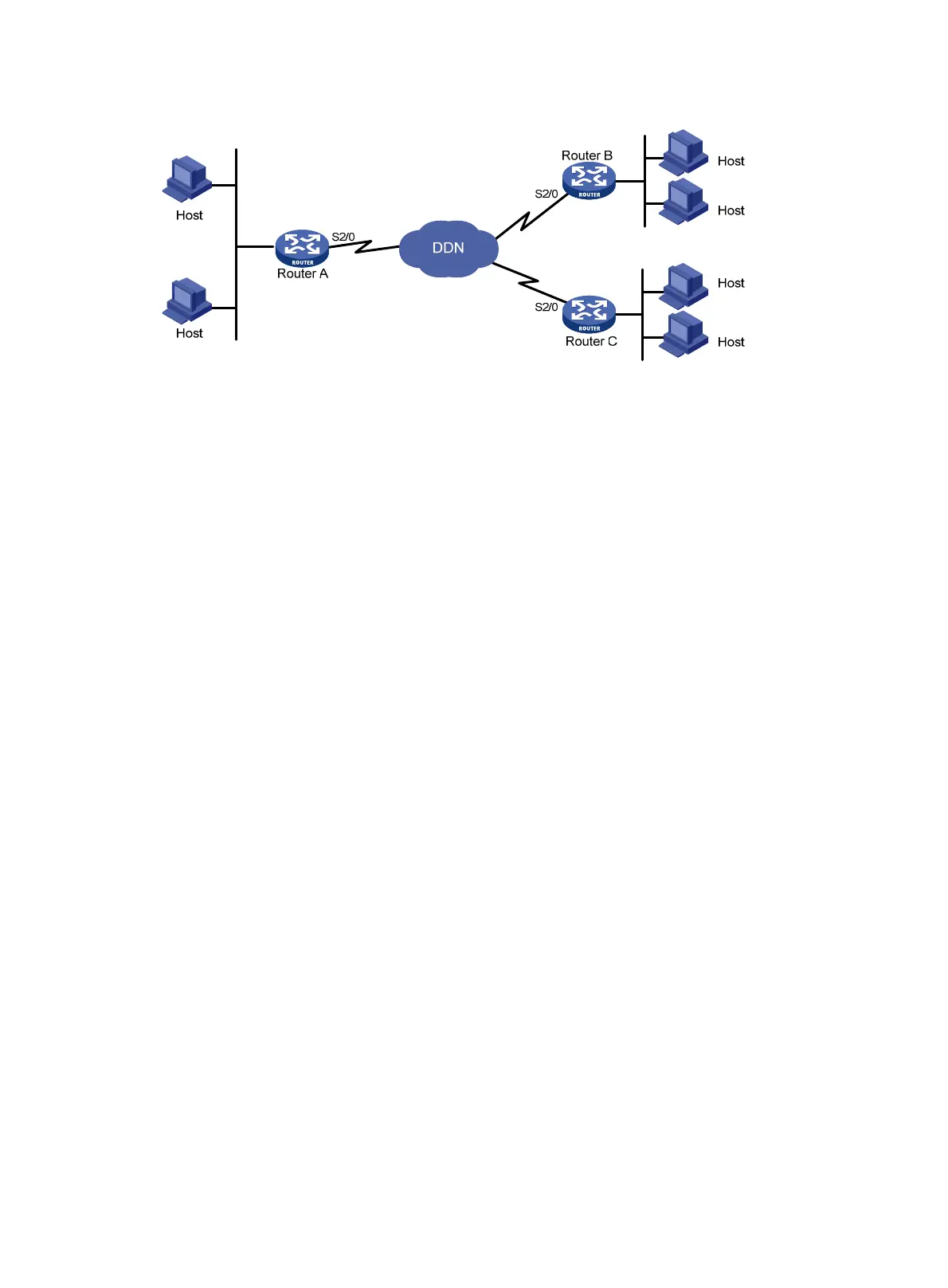
Figure 8 Network diagram
Configuration procedure
1. Configure Router A:
# Create user accounts for Router B and Router C and set the passwords.
<RouterA> system-view
[RouterA] local-user router-b
[RouterA-luser-router-b] password simple router-b
[RouterA-luser-router-b] service-type ppp
[RouterA-luser-router-b] quit
[RouterA] local-user router-c
[RouterA-luser-router-c] password simple router-c
[RouterA-luser-router-c] service-type ppp
[RouterA-luser-router-c] quit
# Create two VT interfaces for the two user accounts.
[RouterA] ppp mp user router-b bind virtual-template 1
[RouterA] ppp mp user router-c bind virtual-template 2
# Configure the VT interfaces.
[RouterA] interface virtual-template 1
[RouterA-Virtual-Template1] ip address 202.38.166.1 255.255.255.0
[RouterA-Virtual-Template1] quit
[RouterA] interface virtual-template 2
[RouterA-Virtual-Template2] ip address 202.38.168.1 255.255.255.0
[RouterA-Virtual-Template2] quit
# Add interfaces Serial 2/0:1, Serial 2/0:2, Serial 2/0:3, and Serial 2/0:4 to MP channels. Take
Serial 2/0:1 as an example.
[RouterA] interface serial 2/0:1
[RouterA-Serial2/0:1] link-protocol ppp
[RouterA-Serial2/0:1] ppp mp
[RouterA-Serial2/0:1] ppp authentication-mode pap domain system
[RouterA-Serial2/0:1] ppp pap local-user router-a password simple router-a
[RouterA-Serial2/0:1] quit
# Configure local authentication for the PPP users in the default ISP domain system.
[RouterA] domain system
[RouterA-isp-system] authentication ppp local
2. Configure Router B:
 Loading...


