6. Operation of ELECYLINDER
341
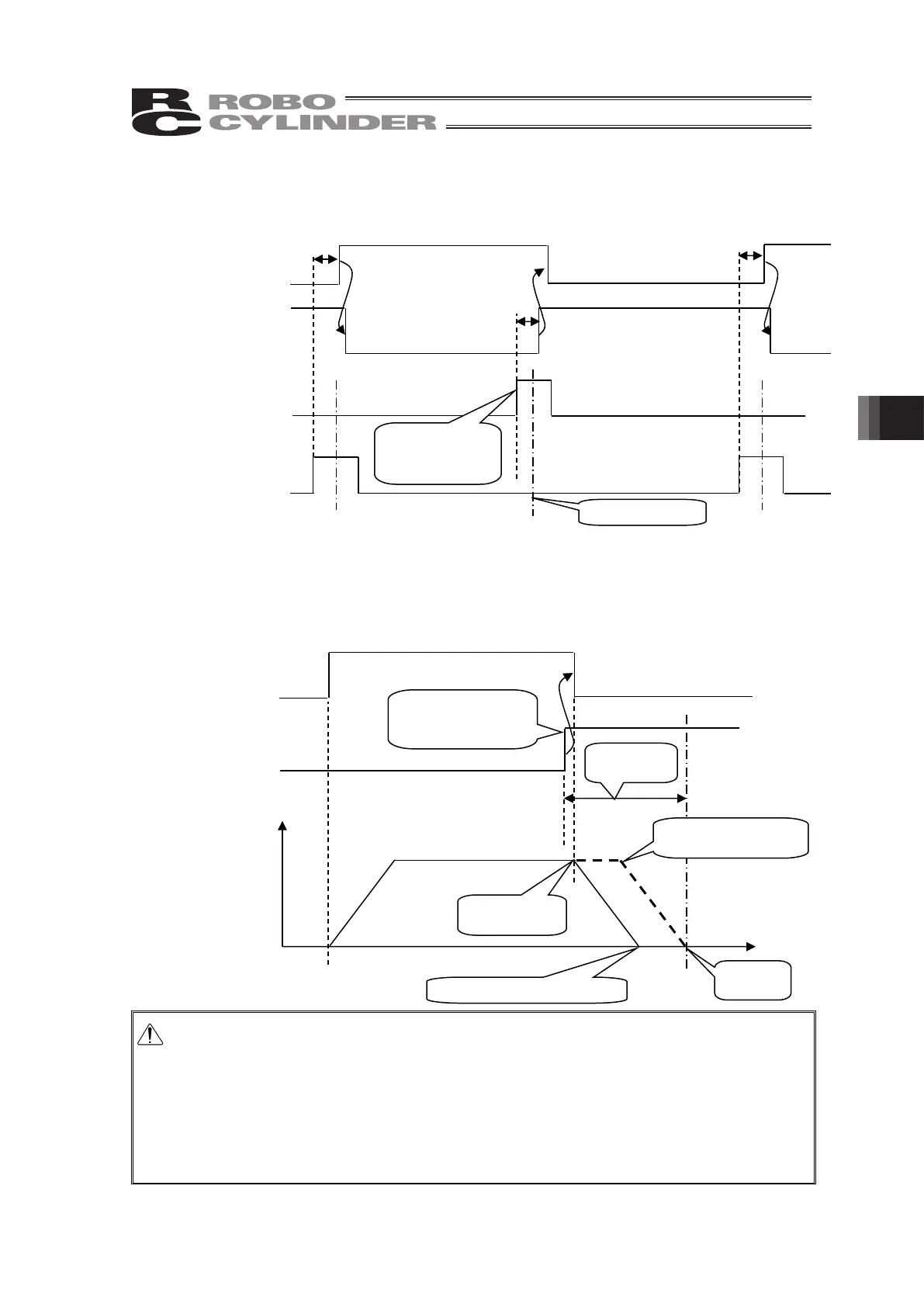
(Example) Repetition of ST0 → ST1 → ST0 →
Insert timer t if necessary.
[Example of stop position when the ST* signal is turned OFF by the LS* signal]
If the detection range is set at a position before the original deceleration start position, the
actuator cannot reach the target position.
Caution: (1) If the ST* signal for the same position is turned ON after the positioning is
completed, the LS* signal remains ON.
(2) LS* Signal turns ON once it gets into the detection range. Therefore, it will also
turns ON while the actuator is in operation if the setting detection range is wide.
(3) Make sure to set ST* Signals interlocked so two or more signals will not turn ON
at the same time. If two or more ST* signals are input simultaneously, they will
be executed according to the following priorities: ST0 → ST1.
(4) LS* signal would not be output if the detection range is set less than the
minimum resolution.
Forward Signal
ST1
(PLC →Controller)
It turns ON when
getting into
detection range.
Target
osition
Forward End Output
LS1
(Controller → PLC)
Operation of Actuator
Stop before target position
Orignal deceleration
start position
Detection
range
Deceleration
start
Velocity
Move
distance
Backward Signal
ST0
(PLC → Controller)
It turns ON when
getting into
detection range.
Target position
Forward End Outpu
LS1
(Controller → PLC)
Forward Signal
ST1
(PLC → Controller)
Backward End Outpu
LS0
(Controller → PLC)
∆t
∆t ∆t
∆t: Time required to certainly reach the target position after the position sensing output LS1 or 0 is turned ON.
 Loading...