112
Program operating mode
Page 7 - Filter
Start Level Swing
This parameter specifies the direction of change in
“Start Level” caused by “AMS1/2”. If “Intensity” is a
positiv
e(+)value,asettingof+willraisetheEGlevel,
and a setting of – will decrease it. With a setting of 0
therewillbenochange.
Attack Level Swing
This parameter specifies the direction of change in
“Attack Level”causedby“AMS1/2”. If“I
ntensity”isa
positive(+)value,asettingof+willraisetheEGlevel,
and a setting of – will decrease it. With a setting of 0
therewillbenochange.
Pitch EG ‘Time’ modulation
AMS(T) (Alternate Modulation Source)
This parameter selects the source that will control the
“Time” parameters of the pitch EG (see “A M S (Alter‐
nateModulationSource)list”onpage12
3).
Intensity (AMS(T) Intensity)
Thisparameterspecifiesthedepthanddirectionof the
effectthat“AMS”willhaveonthe“Time”parameters.
With a setting of 0, the pitch EG times will be just as
specifiedbythe“Attack/Decay/ReleaseTi
me”settings
.
Thealternatemodulationvalueatthemomentthatthe
EGre
acheseach pointwilldetermine theactualvalue
oftheEGtimethatcomesnext.
Forexample,thedecaytimewillbedeterminedby the
alternate modulation va
lue at the moment that the
attacklevelisreached.
Whenthisparameterissettovalue
sof16,33,49,66,82,
or99,thespecifiedEGtimeswillspeedupasmuchas
2,4,8,16,32,or64timesrespectively(orsloweddown
to1/2,1/4,1/8,1/16,1/32,or1/64oftheoriginaltime).
Forexample if“A M S ” issettoVeloc
ity, increasingthe
absolute value of “Intensity” will allow strongly‐
played notes to increase the changes in pitch EG
“Time”values.Thedirectionofthe changeisspecified
by“AttackTimeSwi
ng”and“Decay TimeSwing”.As
you play more so
ftly, the pitch EG times will more
closelyapproachtheactualsettingsofthepitchEG.
‐99…+99 Parametervalue.
Attack Time Swing
This parameter specifies the direction in which “A M S ”
will affect the “Attack Time” parameter. With positive
(+)va
luesof“Intensity”,asettingof+willcausethetime
tobelengthened,andasettingof–willcausethetimeto
beshortened.Withasettingof0therewillbenochange.
Decay Time Swing
Specify the direction in which “A M S ” will affect the
“DecayTime”.Withpositive(+
)valuesof“Intensity”,a
settingof+willcausethetimetobelengthened,anda
settingof–willcausethetimetobeshortened.Witha
settingof0therewillbenochange.
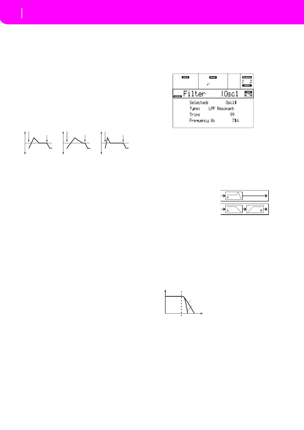
PAGE 7 - FILTER
Here you can makesettings for the filtersthat will be
used by the oscillators. You can select either a 24 dB/
octave low pass filter with resonance, or a series con‐
nection of a12 dB/oct
ave low pass filter and a 12 dB
/
octavehighpassfilter.
Selected
Usethisparametertoselectanoscillatortoputinedit.
Alternatively,youcanselectoscillatorsusingtheF‐1–F‐
4buttons.
Filter Type
Thisparameterselectsthetypeoffilter(LowPassRes‐
onant,Low Pass&High Pass) for the se
lected oscilla‐
tor. When the Low Pass & High Pass filter type
is
selected,thefilterBwillbeactivated.
Trim
Use this parameter to adjust the level at which the
audiosignaloutputfromtheselectedoscillatorisinput
tofilterA.
Note:Ifthisvalueisraised,thesoundmaydistortifReso‐
nanceissettoahi
ghvalueorwhenyouplayachord.
00…9
9 Trimlevel.
Frequency A (Cutoff Frequency A)
This parameter specifies the cutoff frequency of filter
A.
00…99 Cutofffrequencyvalue.
Resonance A
The resonance emphasizes the overtone components
that lie in the region of the cutoff frequency specified
by “Frequency”, producing a more distinctive sound.
Increasingthisvaluewillproduceastrongereffect.
00…99 Resonancevalue.
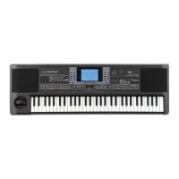
Pitch EG changes (Time) (AMS = Velocity, Intensity = positive (+) value)
Note-on
Note-off
Note-on
Note-off
Note-on
Note-off
A note played softly with Attack
Ti S i t t + d
A note played strongly with
Att k Ti S i t t + d
A note played strongly with
Att k Ti S i t t d
Low Pass Resonance: 24 dB/octave low
pass filter with resonance
Low Pass & High Pass: 12 dB/octave
low pass filter and 12 dB/octave high pass
filter in series
Frequency
Level
Low Pass
12dB/oct
24dB/oct
This is a filter that cuts the
high-frequency region above the cutoff
frequency.
This is the most common type of filter,
and is used to cut part of the overtone
components, making an originally bright
timbre sound more mellow (darker).
When the “Filter Type” is Low Pass
Resonance, the cutoff will have a
steeper slope.