115
Program operating mode
Page 10 - Filter LFO2
Intensity to B
Specifythedepthanddirectionofthemodulationthat
LFO1 willhaveonthe cutofffrequencyof filter B(see
“IntensitytoA”).
‐99…+99 Parametervalue.
Joystick –Y to A
BymovingthejoystickintheYdirection(towardyour‐
self),youcan controlthe depthatwhich LFO1 modu‐
lates the cutoff frequency of fil
ter A. This parameter
specif
iesthedepthanddirectionofthecontrol.
Highersettingsofthisparameterwillprod
ucegreater
increases in the effect of LFO1 on the filter when the
joystickismovedtowardyourself.
‐99…+99 Parametervalue.
Joystick –Y to B
BymovingthejoystickintheYdirection(towardyour‐
self),youcan controlthe depthatwhich LFO1 modu‐
lates the cutoff frequency of filt
er B. This parameter
specif
ies the depth and direction of the control (see
“Joystick–YtoA”).
Filter LFO1 modulation
AMS (Alternate Modulation Source)
Selectasourcethatwillcontrolthedepthanddirection
ofcutofffrequencychangeforbothfiltersAandB.See
“A M S (AlternateModulationSou
rce)list”.
Intensity to A
Specifies the depth and direction of the effect that
“A M S ” willhaveonfilterA.
Forexampleif“A M S ” isJoy st
ick+Y,highersettingsof
thisparameterwillallowgreaterchange tobeapplied
toLFO1whenyoupushthejoystick.
‐99…+99 Parametervalue.
Intensity to B
Specifies the depth and direction of the effect that
“A M S ” willhaveonfilterB(see“IntensitytoA”).
PAGE 10 - FILTER LFO2
Adjuststhedepth ofthecyclic modulationappliedby
LFO2(seton“Page18‐LFO2”)tothecutofffrequency
offiltersAandB.Formoreinformationontheparame‐
terssee“P
age9‐FilterLFO1”onpage114.
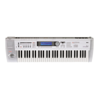
PAGE 11 - FILTER EG
Here you can make settings for the EG that will pro‐
duce time‐varying changes in the cutoff frequ
ency of
filtersAandBfortheselectedoscillator.Thedepthof
theeffectthatthesesettingswillhaveonthe filtercut‐
off frequ
ency is determined by the “Velocity” and
“Intensity”parameters.
Selected
Usethisparametertoselectanoscillatortoputinedit.
Alternatively,youcanselectoscillatorsusingtheF‐1–F‐
4buttons.
Filter envelope
Start/Attack/Break/Sustain/Release Level
These are the envelope segment levels. The result will
dependonthefilterthatwasselectedin“FilterType”.For
example,with the Low PassResonance filter,posit
ive(+)
valuesofEGIntensitywillcausethetonetobebrightened
bypositive(+)levels,anddarkenedbynegative(–)levels.
‐99…+99 Levelvalue.
Start Level
Thisparameterspecifiesthechangeincutofffrequency
atthetimeofnote‐on.
Attack Level
Thisparameterspecifiesthechangeincutofffrequency
aftertheattacktimehaselapsed.
Break Point Level
Thisparameterspecifiesthechangeincutofffrequency
afterthedecaytimehaselapsed.
Sustain Level
Thisparameterspecifiesthechangeincutofffrequency
that will be maintained from after the slope ti me has
elapseduntilnote‐offoccurs.
Release Level
Thisparameterspecifiesthechangeincutofffrequency
thatwilloccurwhenthereleasetimehaselapsed.
Attack/Decay/Slope/Release Time
Theseparametersspecifythetimeoverwhichthefilter
changewilloccur.
0…99 Timevalue.
Change in cutoff
Low setting High setting
Note-on
Note-off
Attack
Time
Start
Level
Decay
Time
Release
Time
Release
Level
Attack Level
The specified
cutoff
frequency
Sustain Level
Time
Break
Point
Level
Slope
Time