7-12 824 Reference Manual 9/29/09
AC/DC Output Settings - (SSA,
LOG, ISM)
The AC/DC Output on the 824 allows the user to select what
type of signal will be sent out the 3.5mm connector at the
base of the instrument. See the section "AC/DC Output" on
page 6-5 for more details.
Logic Input Setting - (SSA,
LOG, ISM)
The SSA instrument can access the
Logic-input Mode setting through
either the Check or the Setup menus.
The Logic Input sets the functionality of the logic input pin
on the control connector (pin 3). This pin is intended to be
connected to an external switching device—possibly a push-
button switch. The external switching device will either
connect the pin to +5V (pin 6) or unconnected. This signal
may also be supplied from another device that can supply a 0
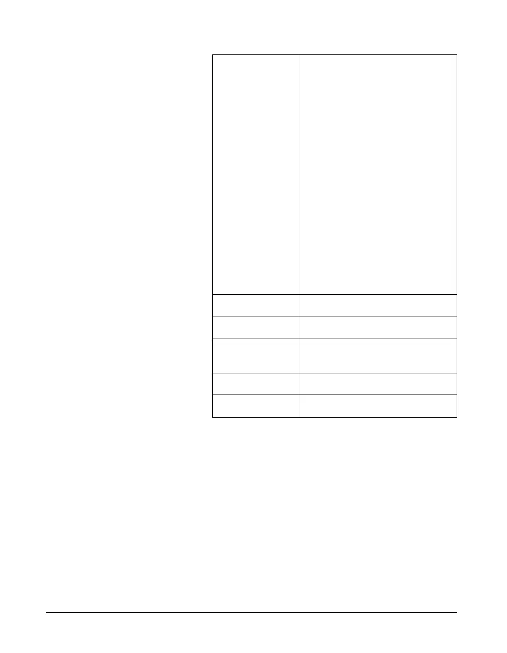
Logic-Out Off
RMS
Peak
R+P
Intv
R+I
P+I
R+P+I
A:D
R+A
P+A
R+P+A
I+A
R+I+A
P+I+A
R+P+I+A
R/S
Excd
Logic-Out Time 0 - 255 sec
Logic-Out #2 Same settings as Logic-Out
Logic-Out #2
Timer
0 - 255 sec
Heater On Yes/No
E.A. Cal Tone Yes/No
NOTE: The Logic-out #2, uses the
Heater output line if set to something
other than off.
NOTE: Menu items Logic-In Mode
through Logic-Out #2 Timer are
system settings that are not stored or
saved with an ID even though they
appear in the SETUP menu