9/29/09 Introduction 1-13
NOTE: See the section "AC/DC Output"
on page 6-5 for more details concerning
the AC/DC outputs.
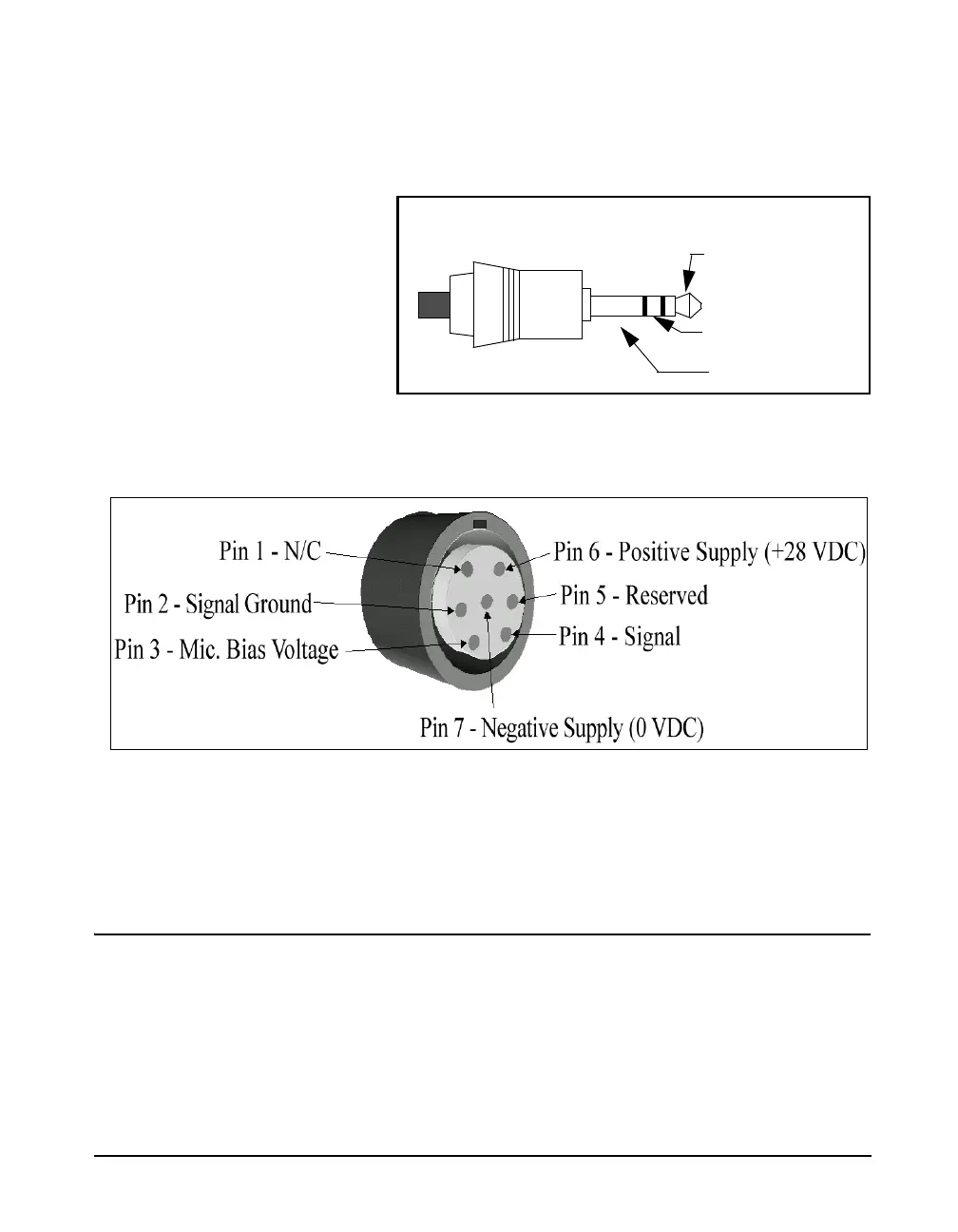
Figure 1-5 AC/DC output connector
Preamplifier Input Connector
The preamplifier input connector accepts the PRM902
preamp.
System Diagram
Figure 1-6, illustrates the acoustic-to-digital signal path in
the System 824. As you can see, incoming sound is first
converted to an electrical signal by the microphone. This
electrical signal is amplified, filtered and then sampled by an
analog-to-digital converter (ADC). The processor then
DC Output
AC Output (Tip)
Ground (-)
(+)(Ring)