1-12 824 Reference Manual 9/29/09
7 - Calibration control output (0 to +5 volts, active high, 10
k)
8 - Heater control output (open drain, +40 Vdc Max, 100
mA Max)
9 - External power input/output (+8 to +15 Vdc)
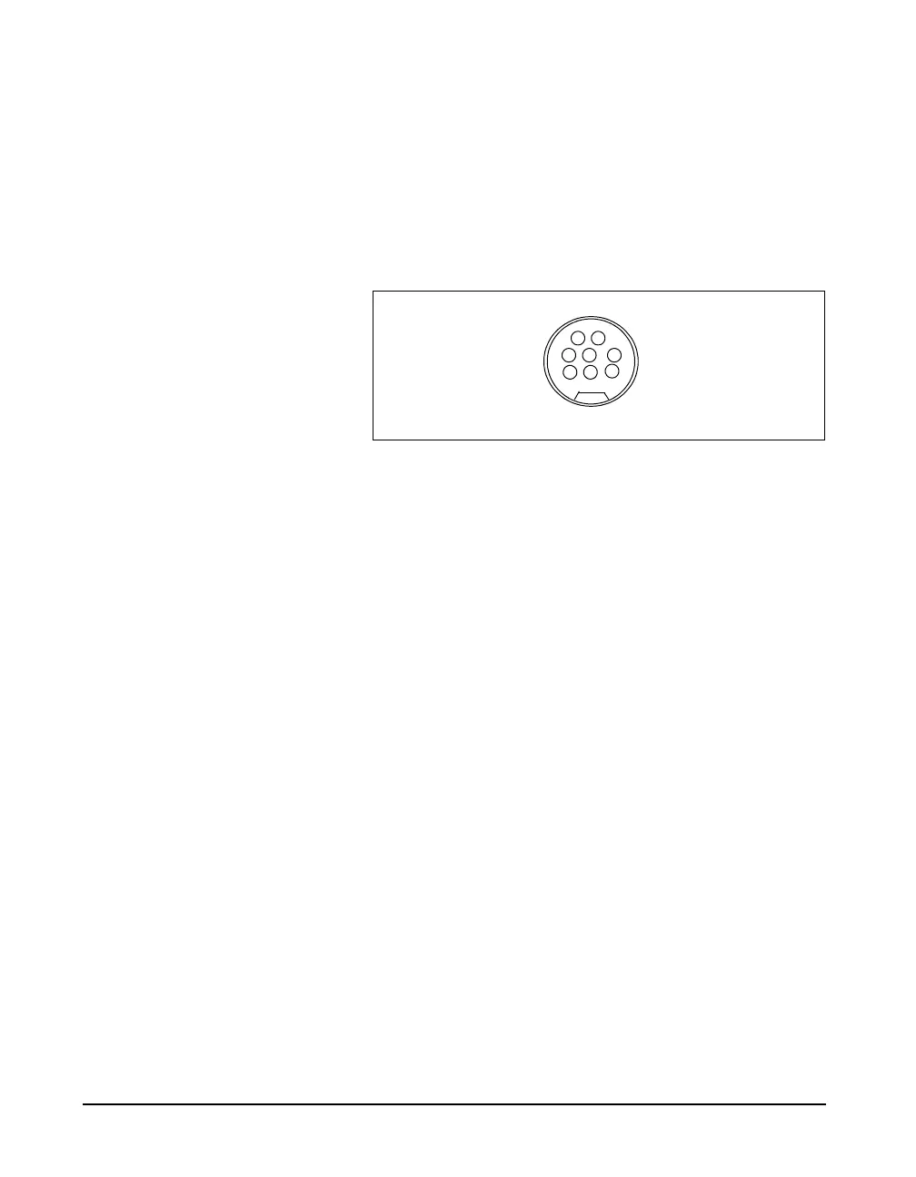
The serial connector is used for computer, printer and
modem communications:
Figure 1-4
The serial connector is an 8 pin mini DIN connector
(AppleTalk
TM
compatible pinout).
1 - Flow control output (RS-232C levels)
2 - Flow control input (RS-232C levels)
3 - Transmit data negative output (RS-232C levels)
4 - Ground
5 - Receive data negative input (RS-422)
6 - Transmit data positive output (RS-422)
7 - Control input (RS-232C levels)
8 - Receive data positive input (RS-422)
Both outputs have a 600 ohm series
resistance.
The AC/DC output connector is used to output the signal
from the System 824 microphone to external devices such as
DAT recorders, real-time analyzers, other sound/vibration
measurement equipment, voltmeters, chart recorders, etc.