9/29/09 Introduction 1-11
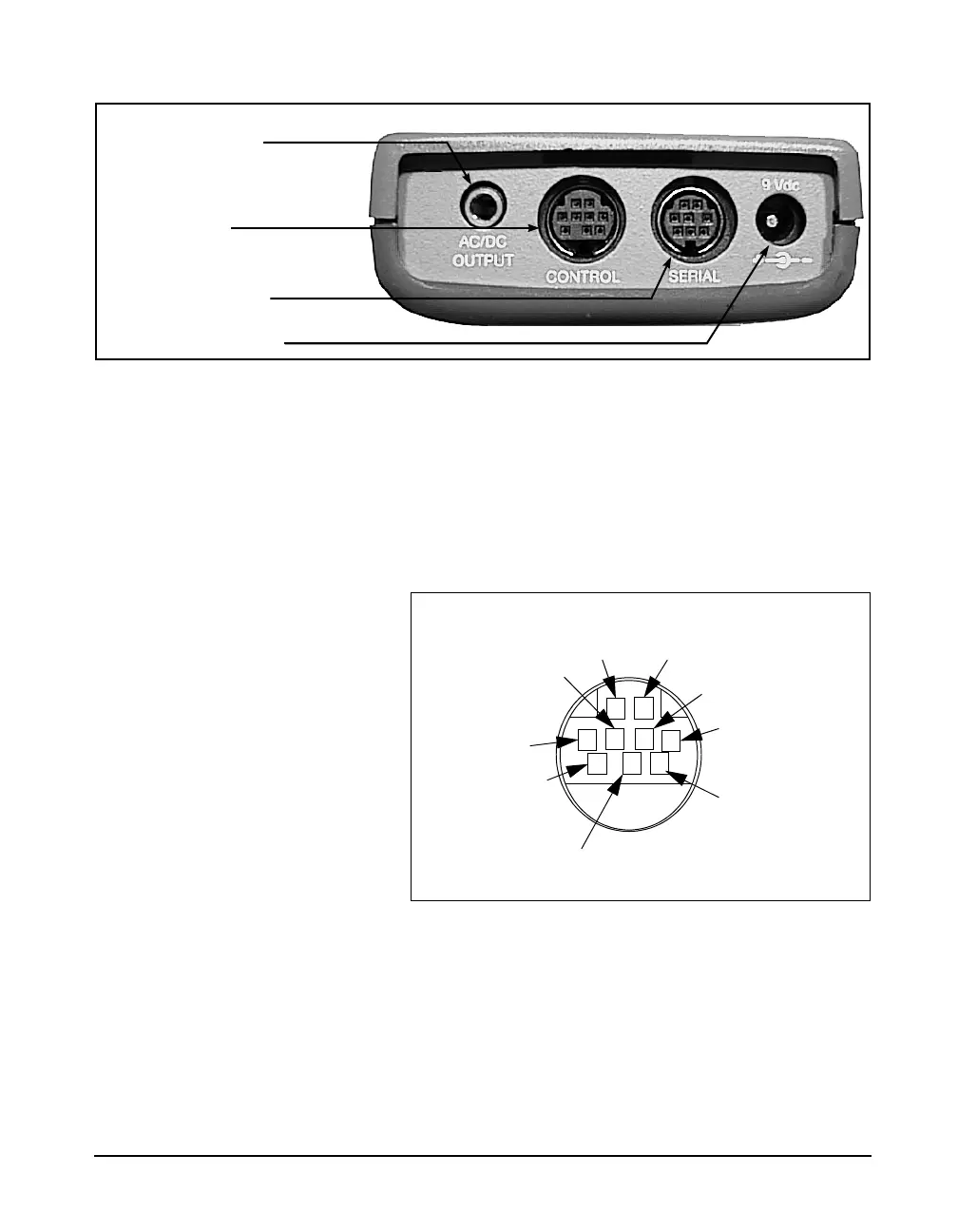
Figure 1-2 The System 824 has a series of connectors located at
the bottom of the device consisting of an AC and DC output
connector, control connector, serial interface connector, and
external DC power connector.
The following is a layout of the control connector, which is
used to control external devices and receive external wind
and control information:
Figure 1-3
9 pin mini DIN control connector; solder view
1 - Ground
2 - Logic output (0 to + 5 volts, active high, through 1 k)
3 - Logic input (0 to + 5 volts, active high, 100 k
load)
4 - Wind speed input (.05 to 10 Vdc peak to peak, 10 k
load)
5 - Wind direction A:D input (0 to 2.5 Vdc, 100 k
load))
6 - Wind direction power (+5 Vdc through 250 )
Control Connector
AC/DC Output Connector
External DC Power Connector
Serial Interface Connector
12
3
4
5
6
7
8
9
Logic Output
Wind Direction Input
Wind Direc Power
Ground
Windspeed
Logic In
Cal Check
Heater Cntrl
Ext Power