Reference run 3: CwRpCcwRnTP
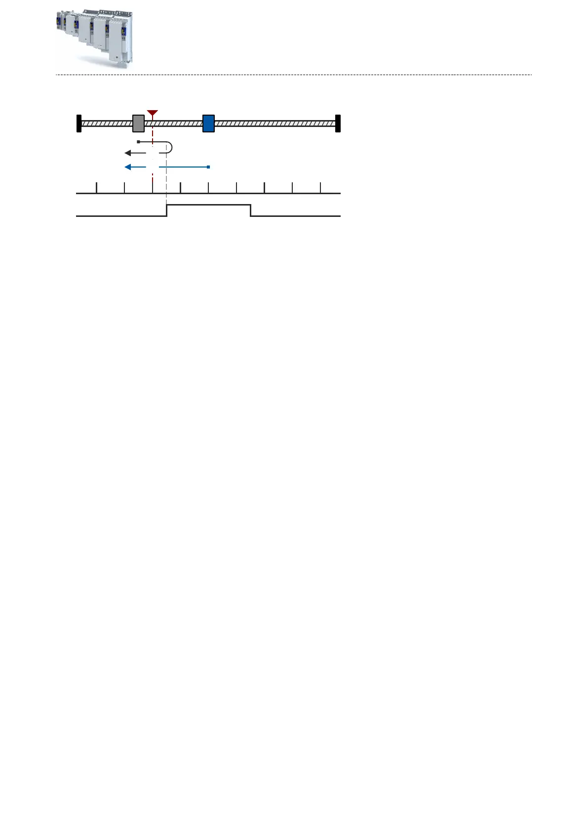
Fig. 9: Posive
direcon with reversing limit switch and negave edge of the reference switch to touch probe
A Touch probe/zero pulse B Reference switch
Sequence of case ①:
The axis has not yet acvated the reference switch:
1.
The machine part mo
ves in posive
direcon with prole data set 1.
2.
The machine part reverses with
posive edge of the reference switch (B) and changes to
prole data set 2.
3.
The negave edge of the reference switch (B) acvates the touch probe detecon.
4.
The f
ollowing posive edge of the encoder zero pulse/touch probe sensor (A) sets the ref-
er
ence.
5.
Further acons can be selected:
•
Drive stops (default seng).
•
Relave posioning around a set target posion.
•
Ab
solute posioning to a set target posion.
Sequence for case ②:
The axis has already acvated the reference switch:
1.
The machine part moves in negave direcon with prole data set 2.
2.
The negave edge of the reference switch (B) acvates the touch probe detecon.
3.
The f
ollowing posive edge of the encoder zero pulse/touch probe sensor (A) sets the ref-
er
ence.
4.
Further acons can be selected:
•
Drive stops (default seng).
•
Relave posioning around a set target posion.
•
Ab
solute posioning to a set target posion.
Technology applicaon (TA) basic sengs
Moon sengs
Homing
63