Diagnostic information 2-91
5061
7
System board—Measure the voltage at connector
JOPP1-2 on the “System board” on page 5-8. The
voltage measures approximately +5 V dc.
Is the voltage correct?
Replace the
operator panel
assembly. See
“Operator panel
assembly
removal” on
page 4-68.
Go to step 8
8
Operator panel cable (operator panel connection)—
Make sure that the operator panel cable is seated
correctly in the connector on the operator panel board.
Is the cable seated correctly?
Go to step 9 Seat the cable
correctly.
9
Operator panel cable—Check continuity of the
operator panel cable.
Is there continuity?
Replace the
system board.
See “System
board removal”
on page 4-90.
Go to “Operator
panel assembly
removal” on
page 4-68, and
replace the
operator panel
cable.
10
System board—A poor ground connection between
pin JOPP1-4 on the operator panel board connector
can cause this symptom. Check for continuity between
pin JOPP1-4 and ground on the board. Go to “System
board” on page 5-8.
Is there continuity?
Go to step 11 Replace the
system board.
See “System
board removal”
on page 4-90.
11
Operator panel cable—Check continuity of the
operator panel cable.
Is there continuity?
Replace the
operator panel
assembly. See
“Operator panel
assembly
removal” on
page 4-68.
Go to “Operator
panel assembly
removal” on
page 4-68 and
replace the
operator panel
cable.
12
Operator panel assembly—Does the operator panel
display all diamonds, with the power on/status LED on
and five beeps?
Go to step 13 Contact your next
level of support.
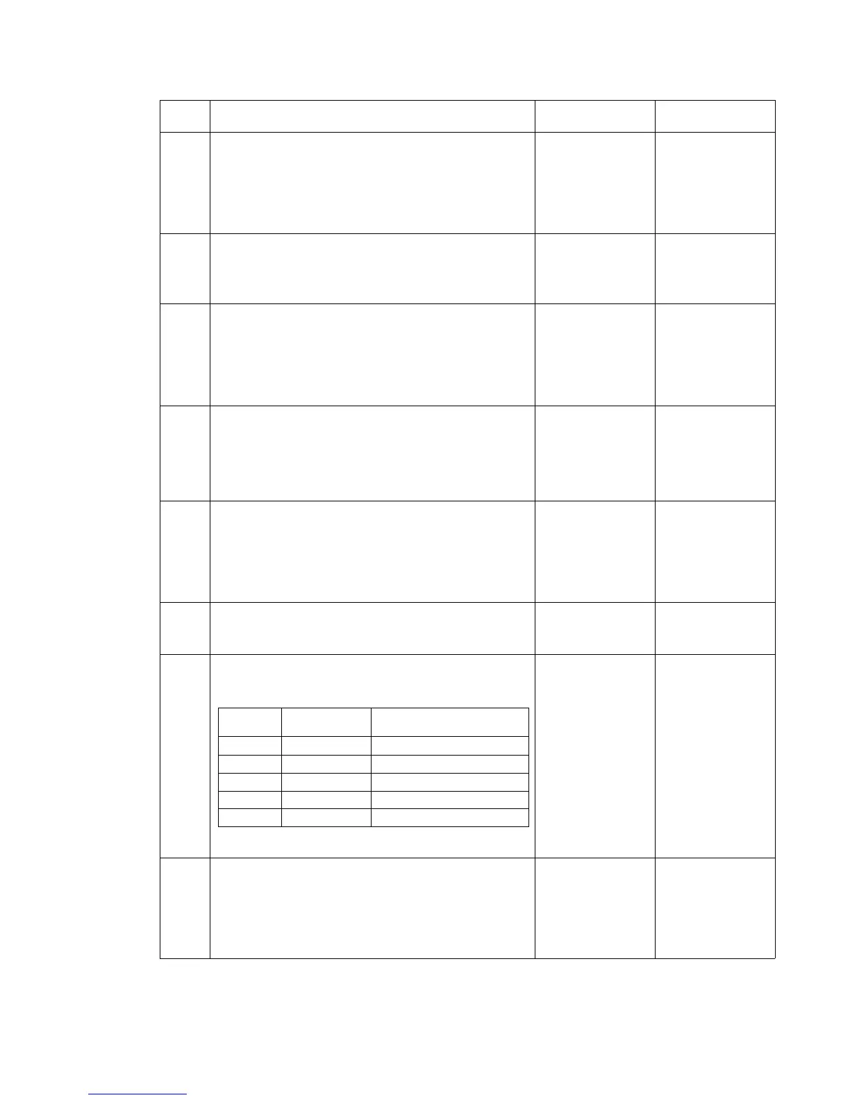
13
Voltage checks at system board connector JOPP1—
Go to “System board” on page 5-8. Check the
voltages on connector JOPP1 as shown:
Are the voltages correct?
Replace the
operator panel
assembly. See
“Operator panel
assembly
removal” on
page 4-68.
Go to step 14
14
Operator panel cable—Check continuity of the
operator panel cable.
Is there continuity?
Replace the
operator panel
assembly. See
“Operator panel
assembly
removal” on
page 4-68.
Go to “Operator
panel assembly
removal” on
page 4-68, and
replace the
operator panel
cable.
Step Actions and questions Yes No
Connector
pin
Voltage (display
static)
Voltage (display active—LCD
Test running)
JOPP1-1 +5 V dc Voltage varies 1.0 to 2.0 V dc
JOPP1-2 +5 V dc +5 V dc
JOPP1-3 +5 V dc Voltage varies 1.0 to 2.4 V dc
JOPP1-4 Ground Ground
JOPP1-5 +5 V dc +5 V dc