Diagnostic information 2-73
5061
500-sheet drawer option service check
If the paper does not feed from the 500-sheet option, see “Autocompensator service check” on page 2-78.
Whenever the 500-sheet tray is removed, use care as the autocompensator may be in its down position which
could result in damage to the autocompensator assembly.
The tray empty sensor, paper low sensor, and pass thru sensor for any installed tray x (x=2 through 4) can be
checked using the “Sensor Test” on page 3-20.
The base printer does not recognize that tray x is installed.
Step Actions and questions Yes No
1 Is tray x the only paper input option that is not
recognized?
Go to step 5 Go to step 2
2
Make sure the printer and any option above tray x is
installed correctly.
Is the printer and any options installed correctly?
Go to step 3 Install the option
correctly, and
recheck.
3
Verify correct installation of the lower options
autoconnect cable to system board connector J20.
Is the cable to J20 installed correctly?
Go to step 4 Install the cable
correctly, and
recheck.
4
Autoconnect cables—check the autoconnect from the
printer or option above tray x. Check for cuts, pinched
wiring, or damage to the contacts in the connector.
Are there any problems with the autoconnect cables?
Repair or replace
as necessary.
Go to step 5
5
Tray x autoconnect cable—check the tray x
autoconnect cable(s) for correct installation at the
tray x system board.
Are the tray x autoconnect cable(s) connected
correctly?
Go to step 6 Install the cables
correctly, and
recheck.
6
Tray x autoconnect cable continuity—Check the
continuity of the Tray x Autoconnect cable(s).
Is there continuity?
Go to step 7 Replace
electronic size
sensing
assembly
(includes the
system board).
7
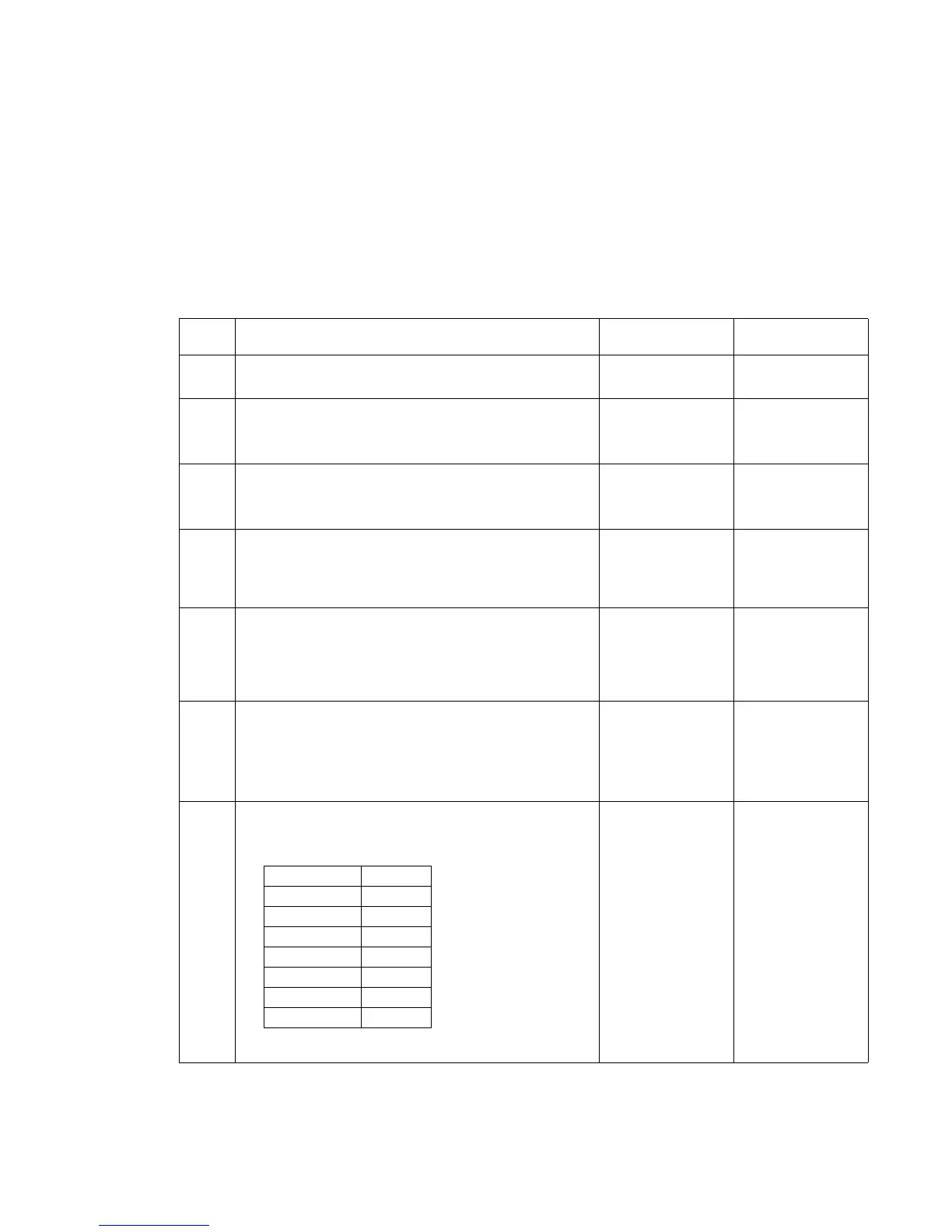
Disconnect J20 from the system board, and check the
voltages on connector J20 on the system board.
Note: All voltages are approximate values:
Are the voltages correct?
Replace
electronic size
sensing
assembly
(includes the tray
system board).
Replace the
system board.
See “System
board removal”
on page 4-90.
Connector pins Voltage
J20-1 +5 V dc
J20-2 Ground
J20-3 Ground
J20-4 +5 V dc
J20-5 +24 V dc
J20-7 +5 V dc
J20-8 +5 V dc