4-90 Service Manual
5061
System board removal
See “System board, network—1xx/3xx only Also order cable tie parts packet (P/N 40X1648)” on page 7-33
for the part numbers.
Note: For a color image of the cabling, see “System board cabling reference” on page 5-6.
Warning: When replacing any one of the following components:
• Operator panel assembly
• System board assembly
• Media size sensing assembly
Only replace one component at a time. Replace the required component, and perform a POR before replacing a
second component listed above. If this procedure is not followed, the printer will be rendered inoperable. Never
replace two or more of the components listed above without a POR after installing each one, or the printer will be
rendered inoperable.
Warning: Never install and remove components listed above as a method of troubleshooting components.
Once a component has been installed in a printer, it cannot be used in another printer. It must be
returned to the manufacturer.
1. Remove the outer system board shield. See “Outer system board shield removal” on page 4-69.
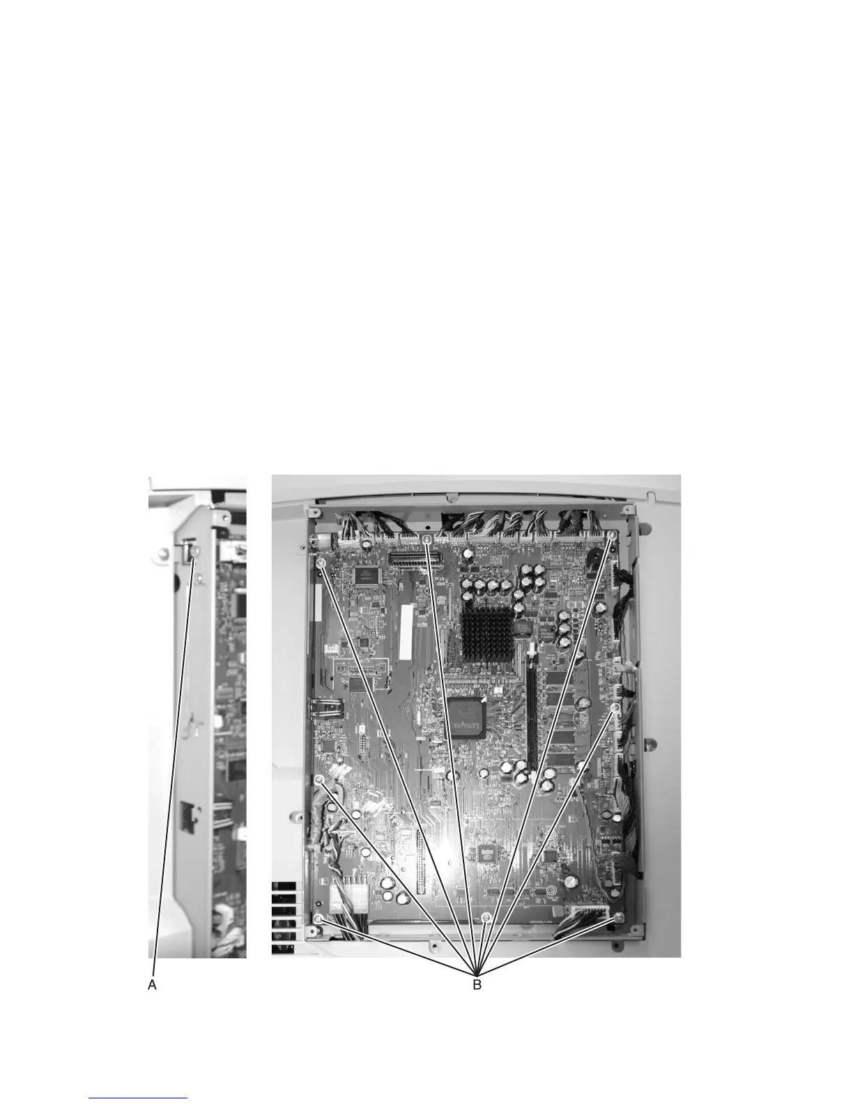
2. Disconnect all the cables from the system board.
3. Remove the USB screw (A).
4. Remove the eight screws (B) type “232” on page 4-3 from the system board.