Diagnostic aids 3-5
5061
If the image is well developed on the PC drum, but the same plane is missing or faded on the ITU belt, the
following components should be checked:
• Bell cranks—Check the condition of the bell cranks.
• Continuity on the bell crank circuit—Turn the printer off. Using a multimeter, check the continuity between
the rear bell crank contact for the failing color and the respective cable on the transfer HVPS board. See
“Transfer high voltage power supply (HVPS)” on page 5-20.
• Transfer HVPS cable—Make sure that there is no damage to the cable running from the system board to
the transfer HVPS board. Verify the connection at both ends.
• Transfer HVPS board
• Engine board
HCIT standalone test mode
This test lets you check out and test the HCIT (2000-sheet high capacity Input tray) without removing any option
or the base printer mounted above the optional HCIT.
Note: During normal operation, the red LED on the HCIT system board blinks on for one second and off for one
second.
Dip switch settings
Do the following steps to set and run the Test/Diagnostic:
1. Use the Dip Switch Settings table to determine the settings (DSW1 thru DSW4) on the HCIT control board
for the test you want to run.
2. Turn the HCIT power off by moving the LVPS slide switch to the left position.
3. Press and hold the Push Button Switch PBSW1 while moving the LVPS slide switch to the right position.
The red LED on the HCIT control board comes on.
4. Press PBSW1 to feed paper.
5. Press PBSW1 to stop feeding paper.
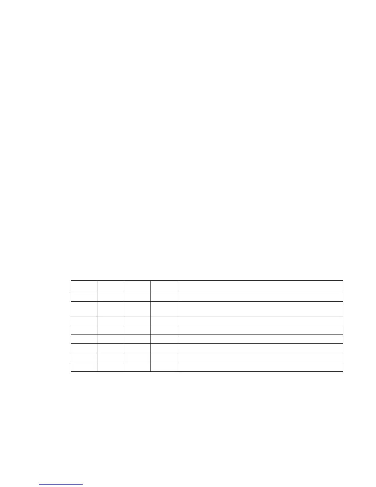
Dip switch settings
DSW1 DSW2 DSW3 DSW4 Mode
Off Off Off N/A Set for shipping
Off Off On N/A The Mirror Reflection Sensors must be adjusted anytime the
sensors are replaced.
Off On Off N/A EEPROM Initialize
Off On On N/A Not used
On Off Off N/A Paperless Operation Mode
On Off On N/A Self Operation Mode
On On Off N/A Standalone Feeding Operation Mode
On On On N/A Not used