4-2 Service Manual
5061
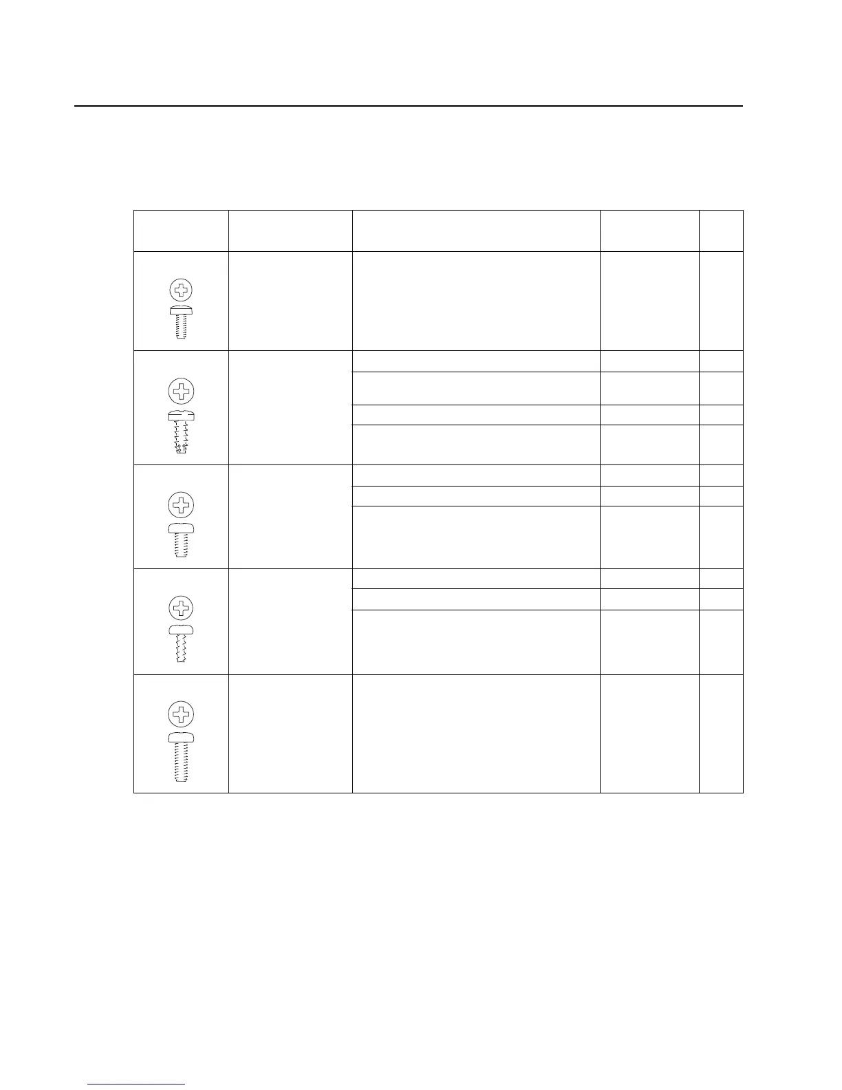
Screw identification table
The following table contains screw types, locations, and quantities necessary to service the printer. Pay careful
attention to each screw type location when doing removals. You must install the correct screw type in each
location during reassembly.
Reference
number
Screw type Location Purpose Qty
002 4-40 Machine Parallel connector to shield Attach 2
102 M3.5x8 mm
Thread Cutting
Cartridge guides to upper frame Attach 8
Upper front cover assembly to cartridge
guides
Attach 4
Front cover pivot to front upper cover Attach 2
Front left light shield to upper front cover
assembly
Attach 1
121 M3.5x6 mm
Machine
LVPS to lower frame Mounting 7
Right rear cover to LVPS Attach 1
HVPS standoffs to upper frame Mounting 4
133 M3x8 mm
Panhead
Door handle to cover Attach 2
Detent housing to cover Attach 1
Door spring shields to cover Attach 4
214 M3.5x10 mm
Machine
ITU motor to gearbox Mounting 4