Repair information 4-53
5061
LVPS assembly removal
See “LVPS assembly” on page 7-31 for the part number.
Note: Set the voltage range switch to the proper power setting for the geographic area you are in.
1. Remove the fuser drive assembly. See “Fuser drive assembly removal” on page 4-46.
2. Remove the rear cover. See “Rear cover removal” on page 4-22.
3. Disconnect the J17 and J18 cables from the system board.
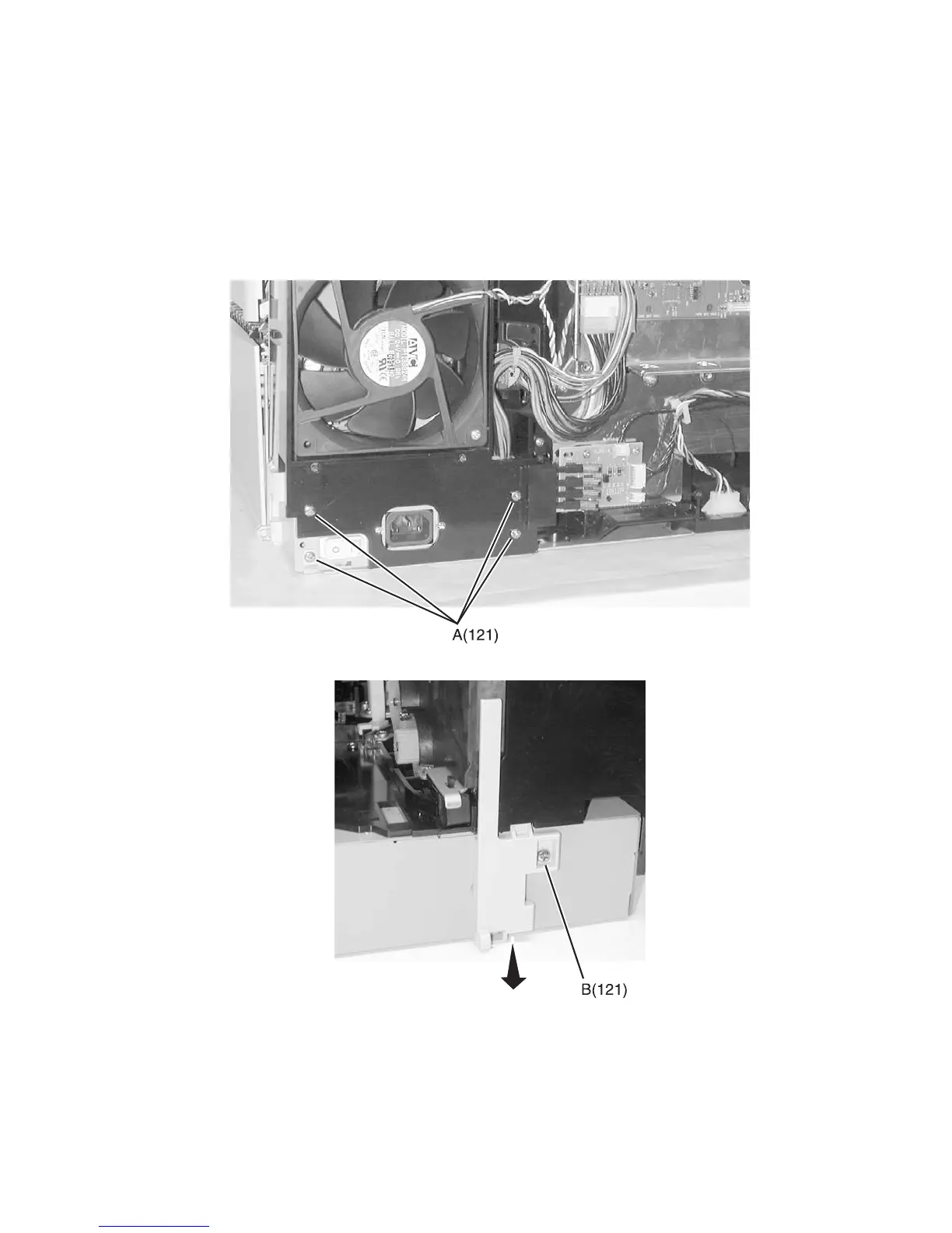
4. Remove the four LVPS screws (A) type “121” on page 4-2 from the rear of the printer.
5. Remove the right rear cover screw (B) type “121” on page 4-2.