Diagnostic information 2-51
5061
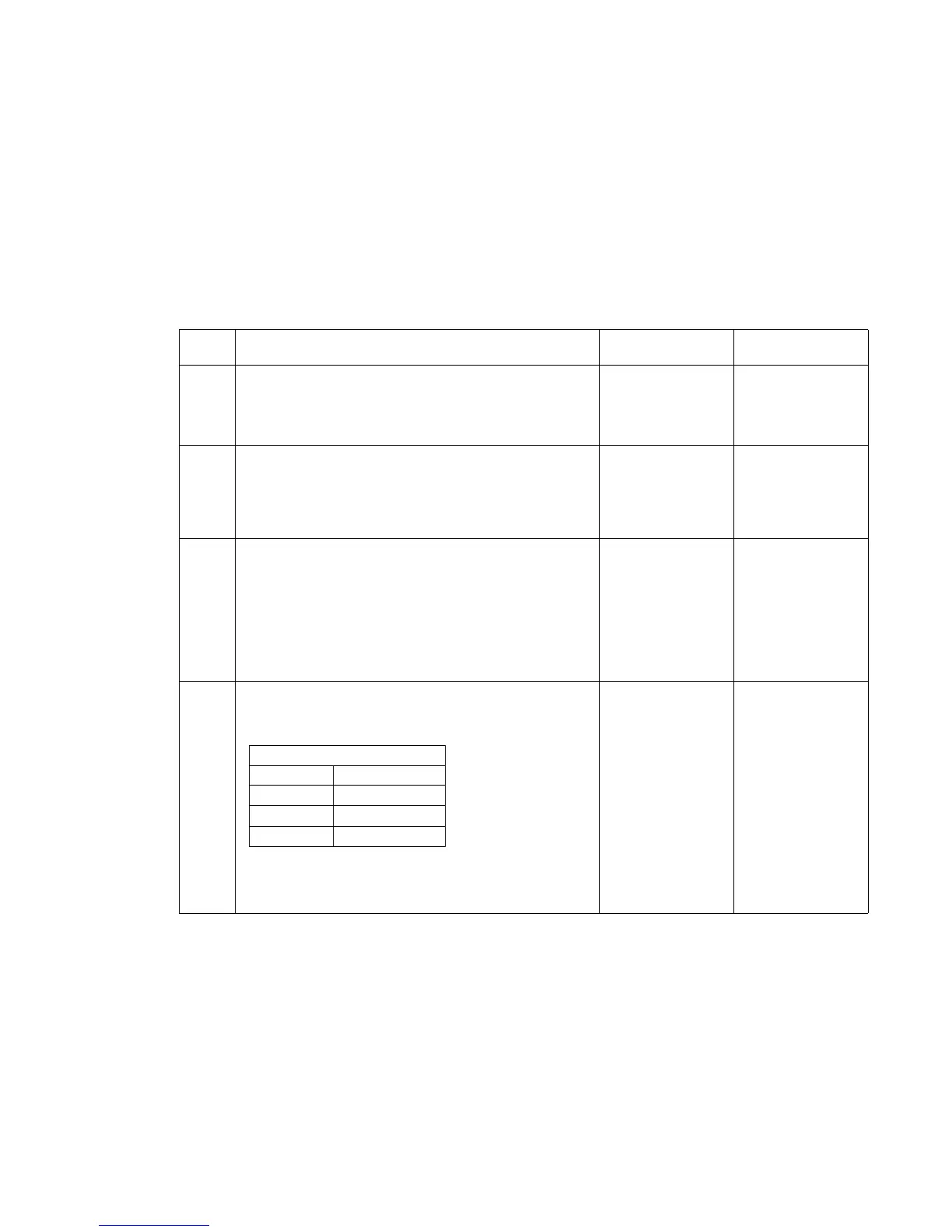
271.xx paper jam service check
Output bin
Note: Before proceeding with this service check, run the Output Bin x Sensor Test and check for the failing
sensor.
Sensor Tests:
XNF Near Full (Upper part of sensor assembly)
F Full (Lower part of sensor assembly)
P Pass Thru Sensor
Step Actions and questions Yes No
1 DC motor cable connection—Make sure the DC motor
connector is correctly installed at J4 on the output
expander option board.
Is the cable installed correctly?
Go to step 2 Install the cable
correctly.
2
DC motor mechanical linkage assembly—Check the
resistance of the motor on the cable connector. Check
the resistance between J4-1 and J4-2. The resistance
measures between 115 ohms and 135 ohms.
Is the resistance correct?
Go to step 3 Replace the DC
motor
mechanical
linkage
assembly.
3
DC motor mechanical linkage assembly—Check for
continuity between J4-1 and J4-2 and the case of the
motor. It measures infinity.
Is there continuity between J4-1 or J4-2 and the case
of the motor?
Note: If the motor is shorted from either J4-1 or J4-2
and the case of the motor, it may be necessary to
replace the output expander control board.
Replace the DC
motor
mechanical
linkage
assembly.
Go to step 4
4
Output expander board—Disconnect the motor cable
from J4, and check the voltages at J4 on the board.
Note: All voltages are approximate values:
Warning: Be careful not to short to adjacent pins on
the connector.
Are the voltages correct?
Replace the DC
motor
mechanical
linkage
assembly.
Replace the
output expander
control board.
J4—Motor cable (motor idle)
J4-1 +24 V dc
J4-2 +24 V dc
J4-5 +5 V dc
J4-6 +5 V dc