4-94 Service Manual
5061
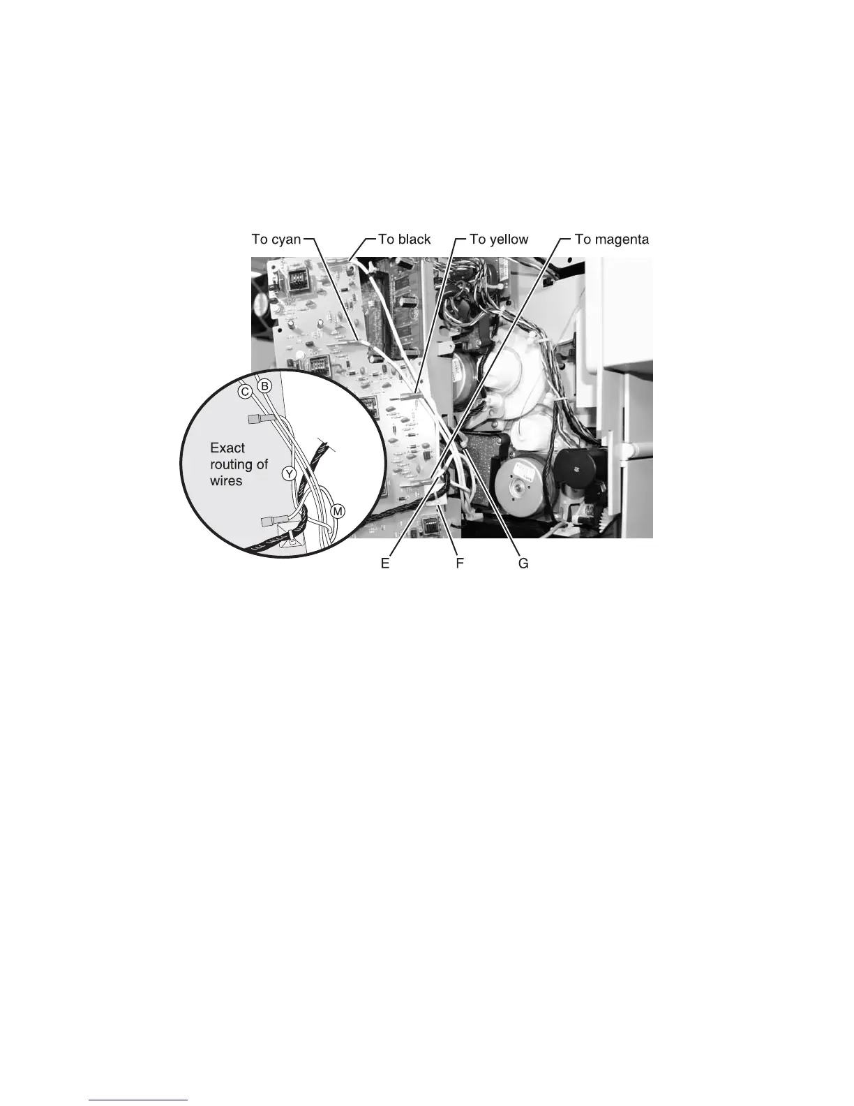
Installation notes
•
To identify the color coded cable bands to the connectors, see “Transfer high voltage power supply
(HVPS)” on page 5-20.
• When installing the transfer HVPS board, route the cable to the HVPS input connector at CN1 (C) over the
cable to the yellow transfer contact (D), under the cable to the magenta transfer contact (E), and attached
to the cable tie (F). This makes sure the toroid (G) does not come into contact with the motor when the
card is in place.