U–36
CONTROL SYSTEM
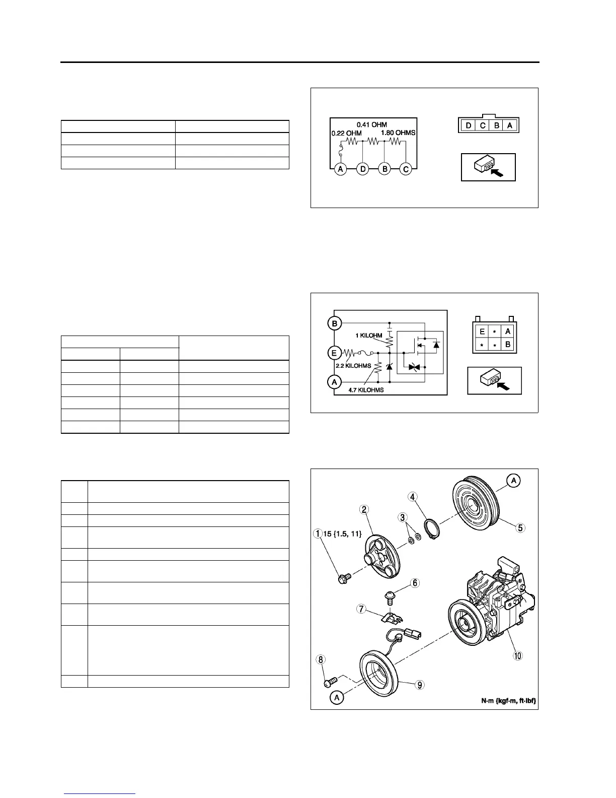
RESISTOR INSPECTION
A6E854061215W02
1. Verify that the resistance between the terminals of
the resistor is as shown in the table.
• If not as specified, replace the resistor.
End Of Sie
POWER MOS FET REMOVAL/INSTALLATION
A6E854061B15W01
(See U–35 RESISTOR REMOVAL/INSTALLATION.)
End Of Sie
POWER MOS FET INSPECTION
A6E854061B15W02
1. Verify that the resistance between the terminals
of the power MOS FET is as shown in the table.
• If not as specified, replace the power MOS
FET.
End Of Sie
MAGNETIC CLUTCH DISASSEMBLY/ASSEMBLY
A6E854061010W01
1. Disassemble in the order indicated in the table.
2. Assemble in the reverse order of disassembly.
3. Adjust the magnetic clutch clearance. (See U–38
MAGNETIC CLUTCH ADJUSTMENT.)
Terminal Resistance (ohm)
A—D0.21—0.23
A—B0.60—0.68
A—C2.29—2.62
A6E8540W012
Ohmmeter lead
Resistance (kilohm)
+ −
AB ∞
AE 6.9
BA Continuity
BE Continuity
EA 6.9
EB ∞
A6E8540W013
1Bolt
(See U–37 Bolt Removal/Installation Note)
2 Pressure plate
3Shim
4 Snap ring
(See U–37 Snap Ring Installation Note)
5 A/C compressor pulley
6Screw
(See U–37 Screw Installation Note)
7Clamp
(See U–37 Clamp Installation Note)
8Screw
(See U–37 Screw Installation Note)
9 Stator and thermal protector
(See U–37 Stator and Thermal Protector Removal
Note)
(See U–37 Stator and Thermal Protector Installation
Note)
10 A/C compressor body
A6E8540W014