FUEL SYSTEM
F–24–14
F
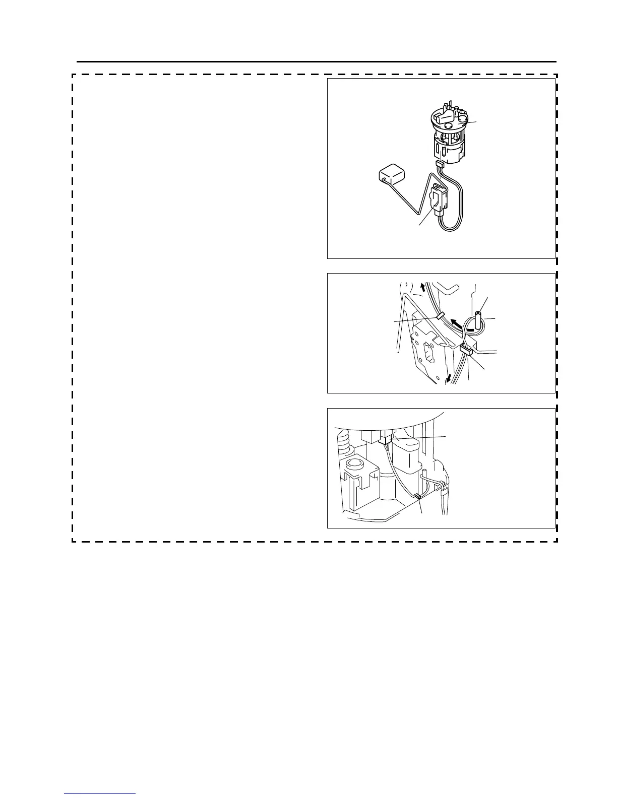
20. Install the fuel gauge sender unit.
21. Perform the following procedure to connect the
fuel gauge sender unit connector, routing the
wiring harness in the proper position.
(1) Install the wiring harness to the reserve cup
clip.
(2) Wrap the wiring harness around projection 1
so that connector-side wiring harness is
routed underside.
(3) Route the wiring harness under projection 2.
(4) Connect the connector.
22. Perform the following procedure to connect the
fuel pump connector, routing the wiring harness in
the proper position.
(1) Position the fuel gauge sender unit installation
surface outward.
FUEL PUMP UNIT
FUEL GAUGE SENDER UNIT
C6E114ZL4002
CONNECTOR-SIDE
PROJECTION 1
PROJECTION 2
CLIP
FUEL GAUGE SENDER UNIT-SIDE
C6E114ZL4023
FUEL GAUGE SENDER
UNIT CONNECTOR
PROJECTION 2
C6E114ZL4024