4. HOW TO MONITOR REDUNTANT SYSTEM
4 - 5
4
HOW TO MONITOR REDUNTANT SYSTEM
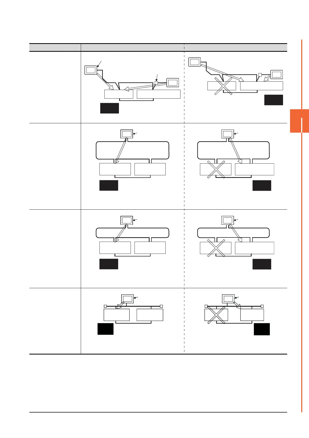
Connection type Before system switching After system switching
• CC-Link connection
(intelligent device station)
• CC-Link connection (Via
G4)
The monitoring target is automatically changed to the control
system PLC CPU.
• MELSECNET/H
connection, MELSECNET/
10 connection
(Network system)
By the Q redundant setting, the GOT automatically changes
the monitoring target to the PLC CPU in the control system.
*2
• CC-Link IE Controller
Network connection
(Network system)
By the Q redundant setting, the GOT automatically changes
the monitoring target to the PLC CPU in the control system.
*2
• Ethernet connection
By the Q redundant setting, the GOT automatically changes
the monitoring target to the PLC CPU in the control system.
*2
Intelligent device station
Master station
GOT1
Standby master station
AJ65BT-G4-S3
CC-Link
GOT2
Control
system
Standby
system
Master station
Standby master station
Control
system
Standby
system
GOT1
CC-Link
GOT2
GOT
Station No.3
(normal station)
MELSECNET/H PLC to PLC network
(MELSECNET/H mode or
MELSECNET/10 mode)
Station No.1
(control station)
Station No.2
(normal station)
Control
system
Standby
system
GOT
Station No.3
(normal station)
MELSECNET/H PLC to PLC network
(MELSECNET/H mode or
MELSECNET/10 mode)
Station No.1
(normal station)
Station No.2
(sub control station)
Control
system
Standby
system
GOT
Station No.3
(normal station)
Station No.1
(control station)
Station No.2
(normal station)
Control
system
Standby
system
CC-Link IE Controller Network
GOT
Station No.3
(normal station)
Station No.1
(normal station)
Station No.2
(sub control station)
Control
system
Standby
system
CC-Link IE Controller Network
GOT
Control
system
Standby
system
Station No. 3
Station No. 1
Station No. 2
Ethernet
GOT
Standby
system
Control
system
Station No. 3
Station
No. 1
Station
No. 2
Ethernet

 Loading...


