4 - 4
4. HOW TO MONITOR REDUNTANT SYSTEM
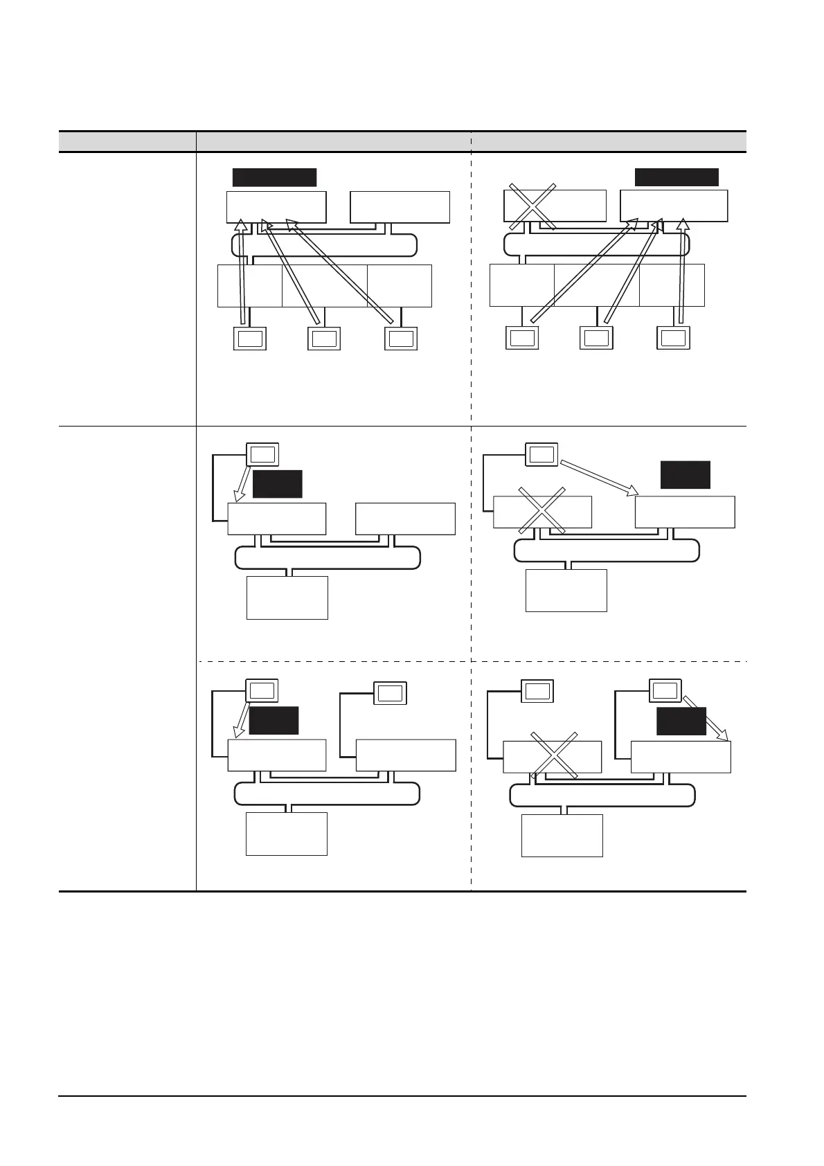
The following table shows the features of each connection method.
Connection type Before system switching After system switching
• Direct CPU connection
(Remote I/O station of
MELSECNET/H network
system)
• Computer link connection
(Serial communication
module mounted on the
remote I/O station on
MELSECNET/H network
system)
• Ethernet connection
(Ethernet module mounted
on the remote I/O station
of the MELSECNET/H
network system)
The monitoring target is automatically changed to the control
system PLC CPU.
• Direct CPU connection
By the Q redundant setting, the GOT automatically changes
the monitoring target to the PLC CPU in the control system.
*1
Monitor the PLC CPU of the control system by GOT1.
Monitor the PLC CPU of the control system by GOT2.
Control system
Multiplexed remote
master station
MELSECNET/H remote I/O network
Standby system
Multiplexed remote
sub master station
GOT1
Direct CPU
connection
GOT3
Ethernet
connection
GOT2
Computer link
connection
Remote
I/O station
Ethernet
module
Serial
communication
module
Standby system
Control system
MELSECNET/H remote I/O network
Multiplexed remote
sub master station
GOT1
Direct CPU
connection
GOT3
Ethernet
connection
GOT2
Computer link
connection
Remote
I/O station
Ethernet
module
Serial
communication
module
Multiplexed remote
master station
GOT
MELSECNET/H remote I/O network
Standby system
Remote I/O
station
Control
system
Multiplexed remote
master station
Multiplexed remote
sub-master station
GOT
MELSECNET/H remote I/O network
Remote I/O
station
Multiplexed remote
master station
Multiplexed remote
sub-master station
Standby system
Control
system
GOT1
GOT2
MELSECNET/H remote I/O network
Remote I/O
station
Multiplexed remote
master station
Multiplexed remote
sub-master station
Standby system
Control
system
GOT1
GOT2
MELSECNET/H remote I/O network
Remote I/O
station
Multiplexed remote
master station
Multiplexed remote
sub-master station
Standby system
Control
system

 Loading...


