4 - 30
4. HOW TO MONITOR REDUNTANT SYSTEM
4.9 Q Redundant Setting
*1 Pair number
Redundant CPU pair means the redundant CPUs (System A / System B) in the redundant system configuration.
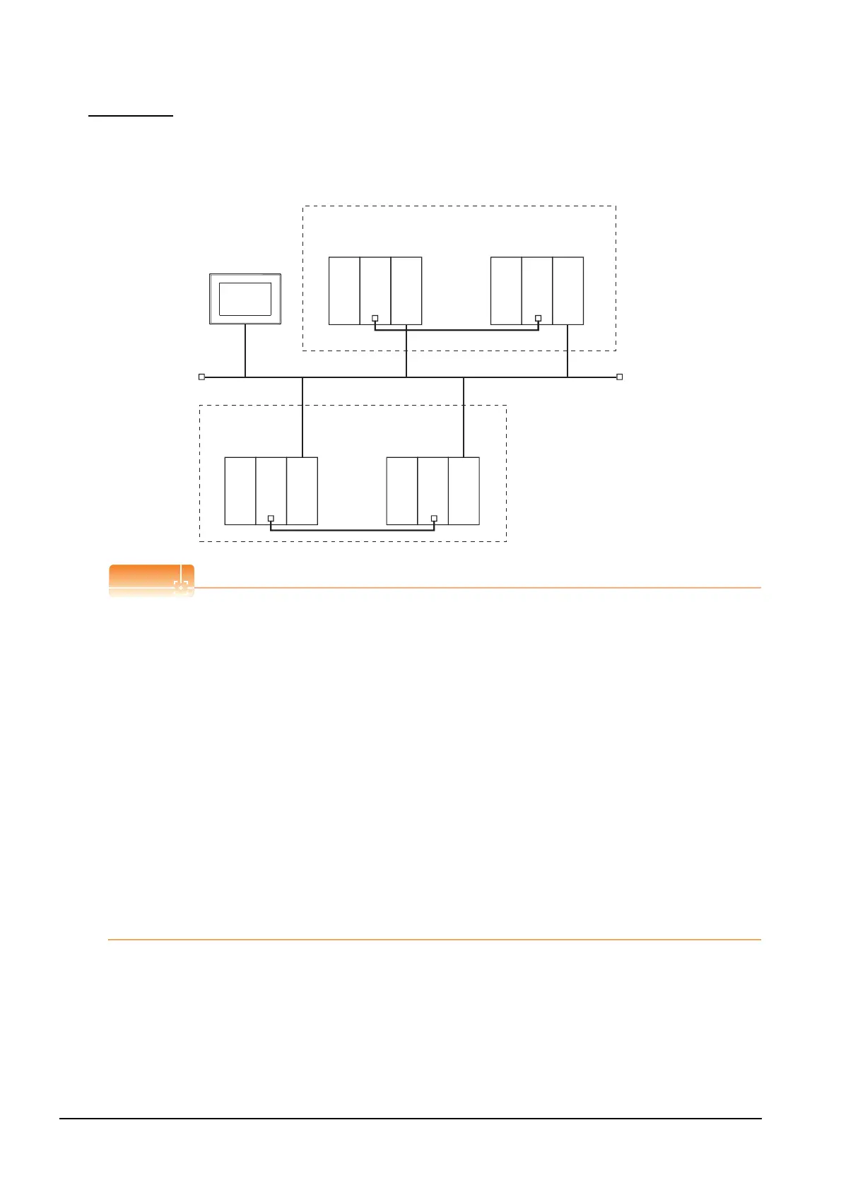
Pair number is the number assigned to each redundant CPU pair.
Example: Ethernet connection (Pair No. 1 and Pair No. 2)
Precautions for making Q redundant setting
Pay attention to the following items when making the Q redundant setting.
• In the setting, station Nos. of the System A CPU and System B CPU must be adjacent numbers to be set as a
pair.
As long as adjacent numbers are used, allocation of them to the System A CPU and System B CPU may be
determined as desired.
• Pairing of the last station No. and station No. 1 (Example: Station No. 64 and station No. 1) is not allowed.
• Make sure that the QCPU in the station for which Q redundant setting is made is a redundant CPU.
If any of the QCPUs to which the Q redundant setting is made is not a redundant CPU, the GOT fails to
automatically change the monitoring target to the control system when the system is switched.
• When making the Q redundant setting for MELSECNET/H, MELSECNET/10, or Ethernet connections, check
the station Nos. of network modules before the setting. If the settings of the Q redundant setting and the actual
network module station Nos. are not matched, the GOT fails to automatically change the monitoring target to
the control system when the system is switched.
• The redundant pair number setting is necessary in the Q redundant setting when the monitoring target changes
automatically at the system switching with the host station specified in Ethernet connection. (The "Target at its
own Station (0-FF)" function of the Q redundant setting is not valid in Ethernet connection.)
• GOT supports the backup mode (separate mode), which is the operation mode of the QCPU redundant system,
and does not support the debug mode.
GOT
<System A>
Redundant CPU pair (No.1)
Ethernet (Network No.1)
Station
No.1
Station
No.5
Station
No.2
<System B>
Q25PRHCPU
Power supply
module
Power supply
module
QJ71E71-100
Q25PRHCPU
QJ71E71-100
<System A>
Redundant CPU
pair (No.2)
Station
No.3
Station
No.4
<System B>
Q25PRHCPU
Power supply
module
Power supply
module
QJ71E71-100
Q25PRHCPU
QJ71E71-100

 Loading...


