9. MELSECNET/H CONNECTION (PLC TO PLC NETWORK), MELSECNET/10 CONNECTION (PLC TO
PLC NETWORK)
9 - 31
MELSECNET/H CONNECTION (PLC TO PLC NETWORK),
MELSECNET/10 CONNECTION (PLC TO PLC NETWORK)
9
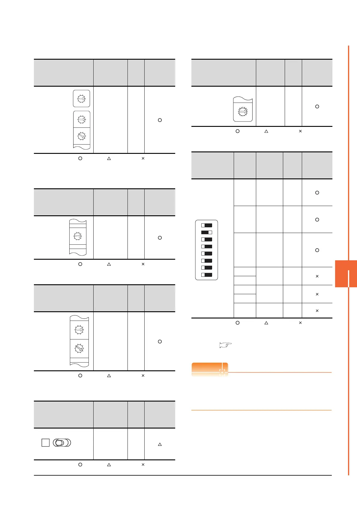
(1) Network number setting switch
: Necessary : As necessary : Not necessary
*1 Specify the same network No. as that of the GOT.
*2 Do not specify a number between 240 and 255.
(2) Group number setting switch
: Necessary : As necessary : Not necessary
(3) Station number setting switch
: Necessary : As necessary : Not necessary
*3 Do not set the same station No. as that of the GOT.
(4) LED indication select switch
: Necessary : As necessary : Not necessary
(5) Mode setting switch
: Necessary : As necessary : Not necessary
(6) Condition setting switches
: Necessary : As necessary : Not necessary
*1 The MELSECNET/10 network module can be communicated
by default parameters.
For details, refer to the following manual.
Type MELSECNET/10 Network system (PLC to PLC
network) Reference Manual
When the switch setting (other than the LED indication
select switch) is changed
Turn the PLC CPU OFF then ON again, or reset the
PLC CPU.
Network number
setting switch
Description
Set
value
Setting
necessity at
GOT
connection
Network
No. setting
(Network
No.1)
*1*2
1
Group number
setting switch
Description
Set
value
Setting
necessity at
GOT
connection
Group No.
setting
(No group
setting)
0
(fixed)
Station number setting switch Description
Set
value
Setting
necessity at
GOT
connection
Station number
setting
(Station No.1)
*3
1
LED indication select switch Description
Set
value
Setting
necessity at
GOT
connection
LED indication
select
L (F.L.)
3
2
0
5
9
4
8
7
6
1
3
2
0
5
9
4
8
7
6
1
3
2
0
5
9
4
8
7
6
1
NETWORK NO.
X100
X10
X1
3
2
0
5
9
4
8
7
6
1
3
2
0
5
9
4
8
7
6
1
STATION.NO.
X10
X1
Mode setting switch Description
Set
value
Setting
necessity at
GOT
connection
Mode setting
(Online)
0
(fixed)
Condition setting
switches
Setting
switch
Description
Set
value
Setting
necessity at
GOT
connection
SW1
Network type
(PLC to PLC
net-work
(PC))
OFF
(fixed)
SW2
Station type
(Control
station
(MNG))
ON
(fixed)
SW3
Parameter
for using
*1
(common
parameter
(PRM))
OFF
(fixed)
SW4
No. of
stations*1
OFF
(fixed)
SW5
SW6
Tota l B / W
points*1
OFF
(fixed)
SW7
SW8 Not used
OFF
(fixed)
F
7
E
6
D
5
C
4
B
3
A
2
9
1
0
8
MODE
0:ONLINE(A.R)
2:OFFLINE

 Loading...


