14 - 44
14. INVERTER CONNECTION
14.6 Device Range that Can Be Set
Inverter (FREQROL 500/700/800 series),
sensorless servo (FREQROL-E700EX)
*1 When creating the screen, designate only either of
programmed operation (PG) device or parameter (Pr)
device.
Do no designate both PG (PG0 to PG89) and Pr (Pr900 to
Pr905) devices.
*2 Only 16-bit (1-word) designation is possible.
*3 Only reading is possible.
*4 When the GOT is connected to the PU connector and the
operation mode is set to the PU operation mode, the multi-
speed operation (W3 to W7, SP121, SP122) cannot be used.
For using the multi-speed operation, follow either of the
operations as below.
• Connect the GOT to the RS-485 terminal and set the
operation mode to the NET operation mode (Computer
link operation mode), and then operate the inverter.
• Change the motor speed with the set frequency (SP109,
SP110), and then operate the inverter with the forward or
reverse rotation (WS1, WS2, SP121, SP122).
*5 Only writing is possible for WS devices.
More than one WS cannot turn on at once.
(Except the turned on WS device, the other WS devices turn
off.)
Bits of SP122 (word device) and SP121 (word device) are
assigned to WS0 to WS7 and WS8 to WS15 respectively.
When more than one WS turns on at once, convert the
values for the bit devices that are assigned to the word
device into values for the word device. Write the converted
values into SP122 or SP121.
• Setting High speed operation command (WS5), Middle
speed operation command (WS4), and Low speed
operation command (WS3)
When setting High speed operation command (WS5),
Middle speed operation command (WS4), and Low speed
operation command (WS3), write numerical values to
device SP122 as necessary.
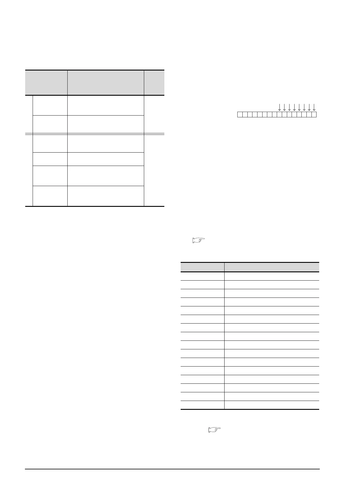
As the following figure shows, each operation mode is
assigned to device SP122.
The following shows an example for Forward rotation
command (WS1) and Low speed operation command
(WS3).
Write [1] to each bit corresponding to Forward rotation
command (WS1) and Low speed operation command
(WS3) of device SP122. The value will be 000AH in this
example. When writing the value to device SP122 actually,
convert 000AH to decimal number and write the value
[10].
When using a WS device, [Alternate] of a bit switch cannot
be used.
Use [Momentary], [Set], and [Reset] for bit switch actions.
The following shows correspondences between virtual
inverter devices used in the GOT and data of the
inverter.
(2) Inverter status monitor
An example with FREQROL-A700 series is shown
below.
For the setting items of other than the FREQROL-A700
series, refer to the following manual.
User's Manual of the used inverter
(communication function (setting item and set
data))
*1 The description (function of input terminal) may be changed
by the parameter of the inverter side. Check the function of
the inverter used.
Inverter User's Manual (Application) Communication
operation and setting
Device name Setting range
Device
No.
represen
tation
Bit device
Inverter
status monitor
(RS)
*3
0-0 RS0 to 0-31 RS15
0-100 RS0 to 0-115 RS15
Decimal
Run command
(WS)
*4*5
0-0 WS0 to 0-31 WS15
0-100 WS0 to 0-115 WS15
Word device
Alarm definition
(A)
*2*3
0-0 A0 to 0-31 A7
0-100 A0 to 0-115 A7
Decimal
Parameter (Pr)
*1*2
0-0 Pr0 to 0-31 Pr1500
0-100 Pr0 to 0-115 Pr1500
Programmed
operation
(PG)
*1*2
0-0 PG0 to 0-31 PG89
0-100 PG0 to 0-115 PG89
Special
parameter
(SP)
*2*4
0-0 SP108 to 0-31 SP127
0-100 SP108 to 0-115 SP127
Device name
Description
*1
RS0 Inverter running (RUN)
RS1 Forward rotation (STF)
RS2 Reverse rotation (STR)
RS3 Up to frequency (SU)
RS4 Overload (OL)
RS5 Instantaneous power failure (IPF)
RS6 Frequency detection (FU)
RS7 Fault (ABC1)
RS8 ABC2
RS9 -
RS10 -
RS11 -
RS12 -
RS13 -
RS14 -
RS15 Fault occurrence
Device SP122
b15 b7 b0
0000000000001010
WS7: Output stop(MRS)
WS6: Second function selection(RT)
WS5: High speed operation command(RH)
WS4: Middle speed operation command(RM)
WS3: Low speed operation command(RL)
WS2: Reverse rotation command(STR)
WS1: Forward rotation command(STF)
WS0: Current input selection(AU)

 Loading...


