15. SERVO AMPLIFIER CONNECTION
15.6 Device Range that Can Be Set
15 - 19
SERVO AMPLIFIER CONNECTION
15
(2) MELSERVO-J2M-P8A
*1 Use PRM0 to PRM29 when writing parameters to the servo
amplifier RAM.
PRM1000 to PRM1029 are used when writing parameters to
E
2
PROM of the servo amplifier.
*2 The GOT cannot read or write data from/to consecutive
devices.
*3 Only reading is possible.
Precautions for SP, OM, and TMO devices
(1) For bit devices
Only writing is possible.
[Alternate] of a bit switch cannot be used.
Use [Set], [Reset], and [Momentary] of a bit
switch.
(2) For word devices
Only writing is possible.
Numerical input cannot be used.
When writing, use [Word Set] of a data set switch.
(a) Servo amplifier request
(b) Operation mode selection
(c) Basic parameter/expansion parameter
*2 For the parameters prefixed by an asterisk (*), setting
becomes effective when the power is turned off once and
back on after setting the parameter data.
(d) Status display
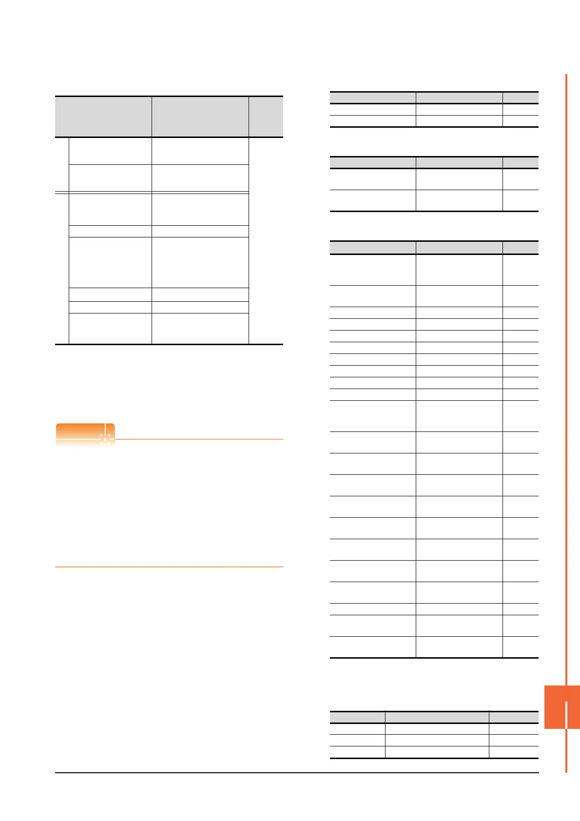
Device name
*2
Setting range available
Device
No.
represent
ation
Bit device
Servo amplifier request
(SP)
SP1 to SP2
Decimal
Operation mode selection
(OM)
OM0 to OM4
Word device
Basic parameter
Expansion parameter
(PRM)
*1
PRM0 to PRM29
PRM1000 to PRM1029
Status display (ST) ST0 to ST2
Alarm (AL)
AL0
AL11 to AL13
AL200 to AL205
AL210 to AL215
AL230 to AL235
External input (DI)
*3
DI0 to DI2
External output (DO) DO0 to DO1
Forced output of signal pin
(for test operation)
(TMO)
TMO0
Device name Item Symbol
SP1 Current alarm clear ―
SP2 Alarm history clear ―
Device name Item Symbol
OM0
Normal mode
(not test operation mode)
―
OM4
Output signal (DO) forced
output
―
Device name Item
Symbol
*2
PRM0, PRM1000
Serial communication
function selection,
alarm history clear
*BPS
PRM1, PRM1001
Regenerative brake option
selection
*REG
PRM2, PRM1002 Function selection 1 *OP1
PRM3, PRM1003 Analog monitor 1 output MD1
PRM4, PRM1004 Analog monitor 2 output MD2
PRM5, PRM1005 Analog monitor 3 output MD3
PRM6, PRM1006 Analog monitor 1 offset MO1
PRM7, PRM1007 Analog monitor 2 offset MO2
PRM8, PRM1008 Analog monitor 3 offset MO3
PRM9, PRM1009 Function selection 2 *OP2
PRM10, PRM1010
Interface unit serial
communication station No.
selection
*ISN
PRM11, PRM1011
Slot 1 serial communication
station No. selection
*DSN1
PRM12, PRM1012
Slot 2 serial communication
station No. selection
*DSM2
PRM13, PRM1013
Slot 3 serial communication
station No. selection
*DSM3
PRM14, PRM1014
Slot 4 serial communication
station No. selection
*DSN4
PRM15, PRM1015
Slot 5 serial communication
station No. selection
*DSN5
PRM16, PRM1016
Slot 6 serial communication
station No. selection
*DSN6
PRM17, PRM1017
Slot 7 serial communication
station No. selection
*DSN7
PRM18, PRM1018
Slot 8 serial communication
station No. selection
*DSN8
PRM19, PRM1019 Parameter write inhibit *BLK
PRM20, PRM1020
Serial communication
time-out selection
SIC
PRM21 to PRM29
PRM1021 to PRM1029
For manufacturer setting ―
Device name Item Symbol
ST0 Regenerative load ratio ―
ST1 Bus voltage ―
ST2 Peak bus voltage ―

 Loading...


