15 - 20
15. SERVO AMPLIFIER CONNECTION
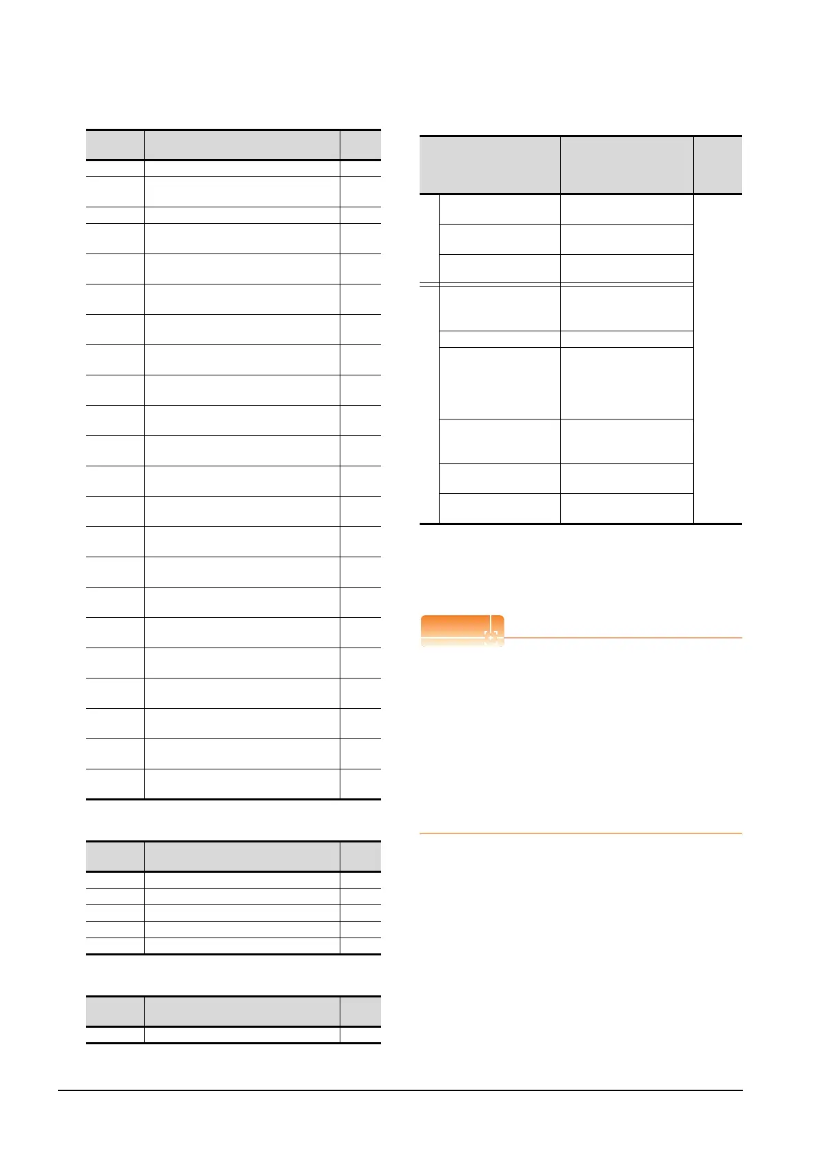
15.6 Device Range that Can Be Set
(e) Alarm
(f) External I/O signal
(g) Forced output of signal pin (for test operation)
(3) MELSERVO-J2M-*DU
*1 Use PRM0 to PRM84 when writing parameters to the servo
amplifier RAM.
PRM1000 to PRM1084 are used when writing parameters to
E
2
PROM of the servo amplifier.
*2 The GOT cannot read or write data from/to consecutive
devices.
Precautions for SP, OM, TMB, TMI, TMO, and TMD
devices
(1) For bit devices
Only writing is possible.
[Alternate] of a bit switch cannot be used.
Use [Set], [Reset], and [Momentary] of a bit
switch.
(2) For word devices
Only writing is possible.
Numerical input cannot be used.
When writing, use [Word Set] of a data set switch.
Device
name
Item Symbol
AL0 Current alarm number ―
AL11
Servo status when alarm occurs
regenerative load factor
―
AL12 Servo status when alarm occurs bus voltage ―
AL13
Servo status when alarm occurs peak bus
voltage
―
AL200
Alarm number from alarm history
most recent alarm
―
AL201
Alarm number from alarm history
first alarm in past
―
AL202
Alarm number from alarm history
second alarm in past
―
AL203
Alarm number from alarm history
third alarm in past
―
AL204
Alarm number from alarm history
fourth alarm in past
―
AL205
Alarm number from alarm history
fifth alarm in past
―
AL210
Alarm occurrence time in alarm history
most recent alarm
―
AL211
Alarm occurrence time in alarm history
first alarm in past
―
AL212
Alarm occurrence time in alarm history
second alarm in past
―
AL213
Alarm occurrence time in alarm history
third alarm in past
―
AL214
Alarm occurrence time in alarm history
fourth alarm in past
―
AL215
Alarm occurrence time in alarm history
fifth alarm in past
―
AL230
Detailed alarm from alarm history
most recent alarm
―
AL231
Detailed alarm from alarm history
first alarm in past
―
AL232
Detailed alarm from alarm history
second alarm in past
―
AL233
Detailed alarm from alarm history
third alarm in past
―
AL234
Detailed alarm from alarm history
fourth alarm in past
―
AL235
Detailed alarm from alarm history
fifth alarm in past
―
Device
name
Item Symbol
DI0 External input pin statuses CN1A/CN1B ―
DI1 External input pin statuses CN5 ―
DI2 External input pin statuses CN4A/CN4B ―
DO0 External output pin statuses CN1A/CN1B ―
DO1 External output pin statuses CN1A/CN1B ―
Device
name
Item Symbol
TMO0 Forced output of signal pin ―
Device name
*2
Setting range
Device
No.
represent
ation
Bit device
Servo amplifier request
(SP)
SP0 to SP6
Decimal
Operation mode selection
(OM)
OM0 to OM4
Instruction demand
(for test operation) (TMB)
TMB0 to TMB1
Word device
Basic parameter
Expansion parameter
(PRM)
*1
PRM0 to PRM84
PRM1000 to PRM1084
Status display (ST) ST0 to ST10
Alarm (AL)
AL0
AL11 to AL21
AL200 to AL205
AL210 to AL215
AL230 to AL235
Input signal for test
operation
(for test operation) (TMI)
TMI0
Forced output of signal pin
(for test operation) (TMO)
TMO0
Set data
(for test operation) (TMD)
TMD0 to TMD2

 Loading...


