15 - 28
15. SERVO AMPLIFIER CONNECTION
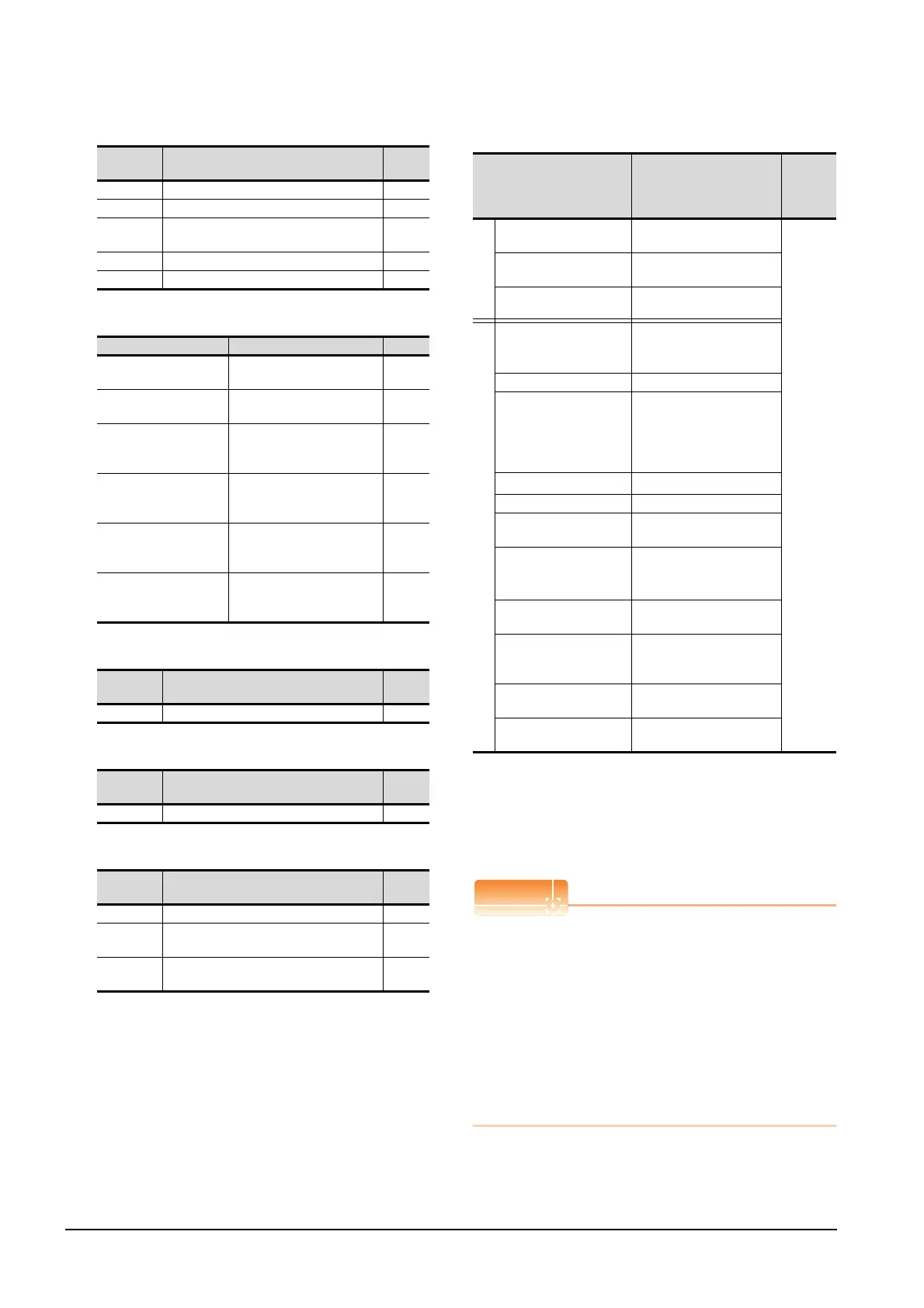
15.6 Device Range that Can Be Set
(g) External I/O signal
(h) Point table (position)
(i) Input signal for test operation (for test operation)
(j) Forced output of signal pin (for test operation)
(k) Set data (for test operation)
(6) MELSERVO-J2S-*CL
*1 PRM0 to PRM90 are used when writing parameters to the
servo amplifier RAM.
PRM1000 to PRM1090 are used when writing parameters to
E
2
PROM of the servo amplifier.
*2 The GOT cannot read or write data from/to consecutive
devices.
*3 Use the integer number when writing parameters to Rx.
*4 Only reading is possible for DI0 to DI1.
Precautions for SP, OM, TMB, TMI, TMO, and TMD
devices
(1) For bit devices
Only writing is possible.
[Alternate] of a bit switch cannot be used.
Use [Set], [Reset], and [Momentary] of a bit
switch.
(2) For word devices
Only writing is possible.
Numerical input cannot be used.
When writing, use [Word Set] of a data set switch.
Device
name
Item Symbol
DI0 Input device statuses ―
DI1 External input pin statuses ―
DI2
Statuses of input devices switched on
through communication
―
DO0 Output device statuses ―
DO1 External output pin statuses ―
Device name Item Symbol
POS1 to POS31,
POS1001 to POS1031
Point table (position)
No. 1 to No. 31
―
SPD1 to SPD31,
SPD1001 to SPD1031
Point table (speed)
No. 1 to No. 31
―
ACT1 to ACT31,
ACT1001 to ACT1031
Point table
(acceleration time constant)
No. 1 to No. 31
―
DCT1 to DCT31,
DCT1001 to DCT1031
Point table
(deceleration time constant)
No. 1 to No. 31
―
DWL1 to DWL31,
DWL1001 to DWL1031
Point table
(dwell)
No. 1 to No. 31
―
AUX1 to AUX31,
AUX1001 to AUX1031
Point table
(auxiliary function)
No. 1 to No. 31
―
Device
name
Item Symbol
TMI0 Input signal for test operation ―
Device
name
Item Symbol
TMO0 Forced output of signal pin ―
Device
name
Item Symbol
TMD0 Writes the speed (test mode) ―
TMD1
Writes the acceleration/deceleration time
constant (test mode)
―
TMD2
Writes the moving distance in pulses (test
mode)
―
Device name
*2
Setting range
Device
No.
represent
ation
Bit device
Servo amplifier request
(SP)
SP0 to SP6
Decimal
Operation mode selection
(OM)
OM0 to OM4
Instruction demand
(for test operation) (TMB)
TMB0 to TMB1
Word device
Basic parameter
/expansion parameter
(PRM)
*1
PRM0 to PRM90
PRM1000 to PRM1090
Status display (ST) ST0 to ST17
Alarm (AL)
AL0 to AL1
AL11 to AL28
AL200 to AL205
AL210 to AL215
AL230 to AL235
External input (DI)
*4
DI0 to DI2
External output(DO) DO0 to DO1
Current position latch data
(LD)
LD1
The value of the general-
purpose register (Rx)
(RR)
*3
RR1 to RR4
RR1001 to RR1004
The value of the general-
purpose register (Dx) (RD)
RD1 to RD4
Input signal for test
operation
(for test operation) (TMI)
TMI0
Forced output of signal pin
(for test operation) (TMO)
TMO0
Set data
(for test operation) (TMD)
TMD0 to TMD2

 Loading...


