15. SERVO AMPLIFIER CONNECTION
15.6 Device Range that Can Be Set
15 - 31
SERVO AMPLIFIER CONNECTION
15
(g) External I/O signal
(h) Current position latch data
(i) The value of the general-purpose register (Rx)
(j) The value of the general-purpose register (Dx)
(k) Input signal for test operation (for test operation)
(l) Forced output of signal pin (for test operation)
(m) Set data (for test operation)
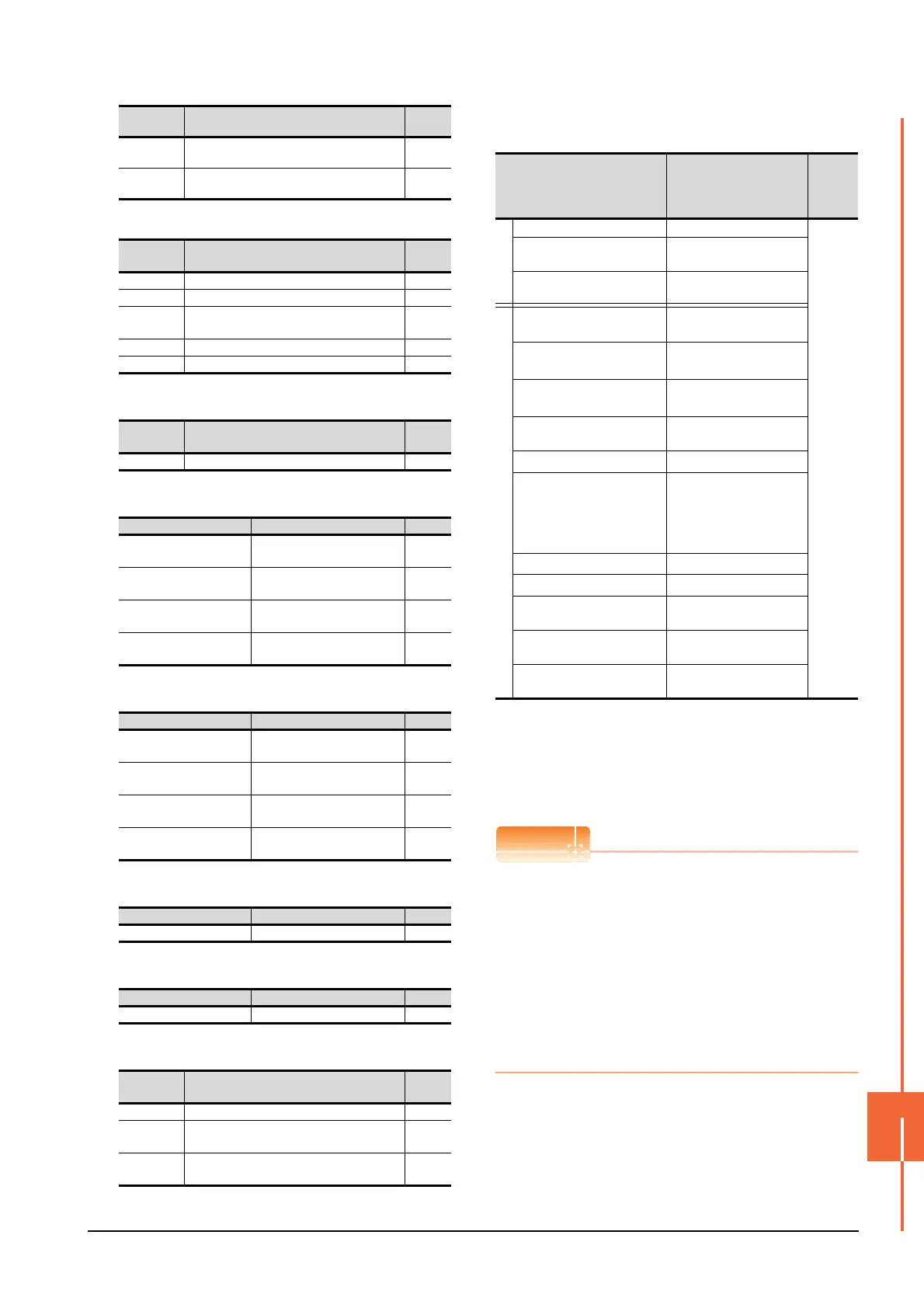
(7) MELSERVO-J3-*A
*1 1 to 50 of PA, PB, PC, and PD are used when writing data to
the servo amplifier RAM.
1001 to 1050 of PA, PB, PC, and PD are used when writing
data to E
2
PROM of the servo amplifier.
*2 The GOT cannot read or write data from/to consecutive
devices.
*3 Only reading is possible.
*4 Only reading is possible for DI0 to DI1.
Precautions for SP, OM, TMB, TMI, TMO, and TMD
devices
(1) For bit devices
Only writing is possible.
[Alternate] of a bit switch cannot be used.
Use [Set], [Reset], and [Momentary] of a bit
switch.
(2) For word devices
Only writing is possible.
Numerical input cannot be used.
When writing, use [Word Set] of a data set switch.
AL234
Detailed alarm from Alarm History
fourth alarm in past
―
AL235
Detailed alarm from Alarm History
fifth alarm in past
―
Device
name
Item Symbol
DI0 Input device statuses ―
DI1 External input pin statuses ―
DI2
Statuses of input devices switched on
through communication
―
DO0 Output device statuses ―
DO1 External output pin statuses ―
Device
name
Item Symbol
LD1 Current position latch data ―
Device name Item Symbol
RR1, RR1001
The value of the general-
purpose register (R1)
―
RR2, RR1002
The value of the general-
purpose register (R2)
―
RR3, RR1003
The value of the general-
purpose register (R3)
―
RR4, RR1004
The value of the general-
purpose register (R4)
―
Device name Item Symbol
RD1
The value of the general-
purpose register (D1)
―
RD2
The value of the general-
purpose register (D2)
―
RD3
The value of the general-
purpose register (D3)
―
RD4
The value of the general-
purpose register (D4)
―
Device name Item Symbol
TMI0 Input signal for test operation ―
Device name Item Symbol
TMO0 Forced output of signal pin ―
Device
name
Item Symbol
TMD0 Writes the speed (test mode) ―
TMD1
Writes the acceleration/deceleration time
constant(test mode)
―
TMD2
Writes the moving distance in pulses(test
mode)
―
Device
name
Item Symbol
Device name
*2
Setting range
Device
No.
represen
tation
Bit device
Servo amplifier request (SP) SP0 to SP6
Decimal
Operation mode selection
(OM)
OM0 to OM4
Instruction demand
(for test operation) (TMB)
TMB1 to TMB6
Word device
Basic setting parameter
(PA)
*1
PA1 to PA19
PA1001 to PA1019
Gain filter parameter
(PB)
*1
PB1 to PB45
PB1001 to PB1045
Extension setting parameter
(PC)
*1
PC1 to PC50
PC1001 to PC1050
I/O setting parameter (PD)
*1
PD1 to PD30
PD1001 to PD1030
Status display (ST)
*3
ST0 to ST14
Alarm (AL)
*3
AL0 to AL1
AL11 to AL25
AL200 to AL205
AL210 to AL215
AL230 to AL235
External input (DI)
*4
DI0 to DI2
External output (DO)
*3
DO0 to DO1
Input signal for test operation
(for test operation) (TMI)
TMI0
Forced output of signal pin
(for test operation) (TMO)
TMO0
Set data
(for test operation) (TMD)
TMD0 to TMD1
TMD3

 Loading...


