19 - 8
19. MULTI-CHANNEL FUNCTION
19.3 GOT Side Settings
(2) Specifications
*1 MELSECNET/H connection, MELSECNET/10 connection, CC-Link IE Controller Network connection, CC-Link connection
(intelligent device station)
*2 Ethernet connection, MODBUS
®
/TCP connection
*3 Gateway function, MES interface function, Ethernet download
*4 Barcode reader, RFID controller, or personal computer (writing remote personal computer operation (serial), FA transparent
function, OS install, project data)
*5 GT15-QBUS2, GT15-ABUS2, GT15-J71GP23-SX, GT15-J71LP23-25, GT15-J71BR13, GT15-J61BT13
*6 GT27-V4-Z, GT27-R2-Z, GT27-V4R1-Z, GT27-ROUT-Z, GT27-MMR-Z
*7 GT15-75QBUSL, GT15-75QBUS2L, GT15-75ABUSL, GT15-75ABUS2L
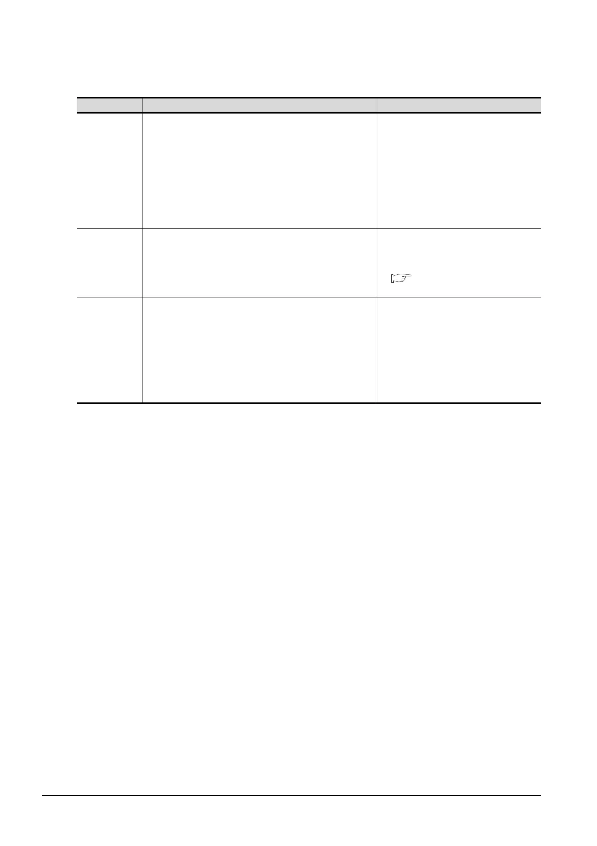
Item Specifications Description
Max. number of
channels
4 channels
• In bus connection and network connection (*1),
only 1 channel can be set for one GOT.
• For the Ethernet connection (*2), up to 4
channels can be set.
• When the Ethernet interface built in the GOT is
used for connection other than communication
with a controller (*3), the connection is not
included in the count of the number of channels.
• The interface used for connecting to an external
device (*4) is not included in the count of the
number of channels.
Max. installable
number of
modules
3
• Multiple identical units can be installed only for
serial communication units.
• It is necessary to calculate the consumed
current.
( This section ■ Calculating consumed
current)
Allowable number
of stages
Max. 3 stages
(2 slots)
• A module that occupies 2 slots (*5, *6, *7) must
be installed at the first stage.
• For the video/RGB display, RGB output, and
multimedia function, install the unit indicated in
*6 at the first stage and the other units at the
second or later stage.
• When a unit indicated in *7 is used, other
extension units cannot be installed.
• The CF card unit must be installed on the last
stage, if used.

 Loading...


