3. ACCESS RANGE FOR MONITORING
3.1 Access Range for Monitoring Stations on Network Systems
3 - 3
3
ACCESS RANGE FOR MONITORING
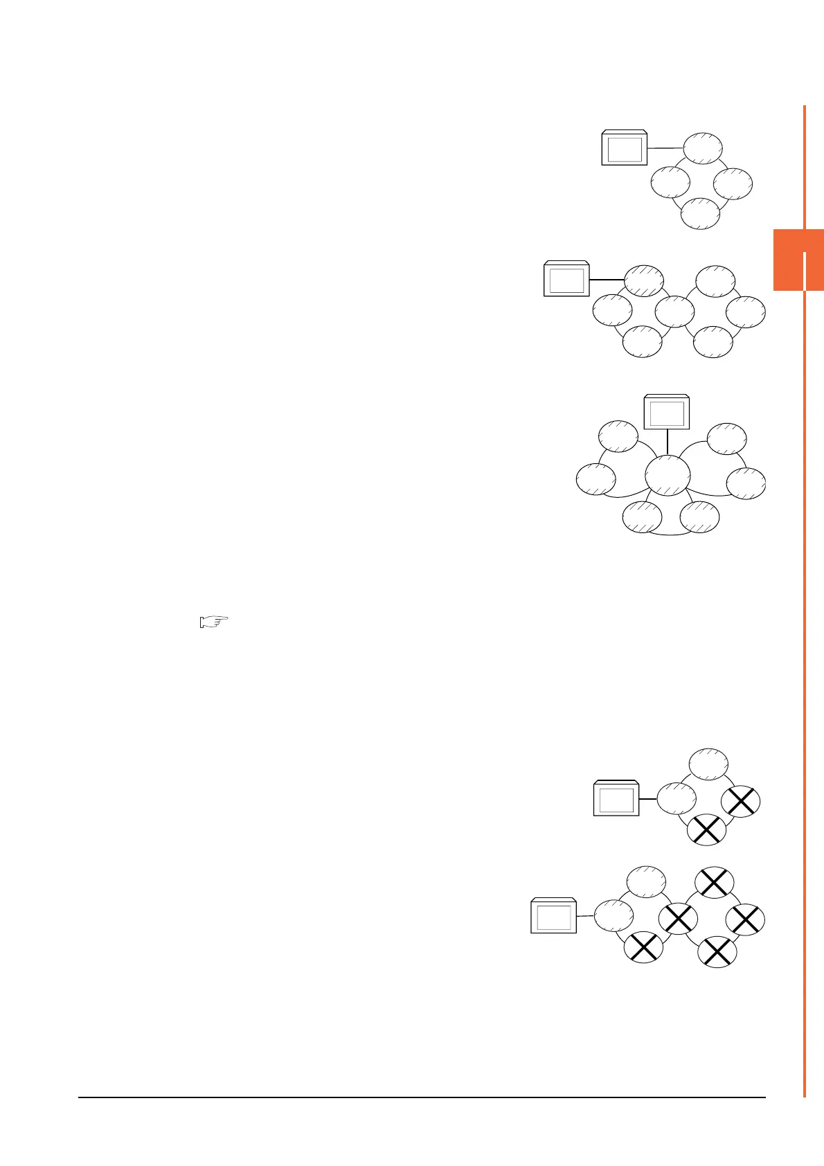
(2) When connecting to QCPU (Q mode)/QnACPU/AnUCPU
• The GOT can monitor the control station and all the normal stations on the
network.
• The GOT can monitor the control station and all the normal
stations on other networks.
(For monitoring stations on other networks, be sure to set the
routing parameter)
When the Universal model QCPU is used as a relay station, the
GOT can monitor stations with the station No.65 or later in the CC-
Link IE controller network.
• When connected to a relay station and the data link system is included,
the master station and local stations can be monitored.
• When connected to a relay station, it is not necessary to designate the
data link parameter [Effective unit number for accessing other stations]
for the PLC CPU of the connected station. (Even if designated, the
parameter is ignored)
• Devices of other stations (other than devices B and W that are allocated by the network parameter) may not
allow monitoring depending on their PLC CPU.
■ Monitor accessible range of other stations and setting method of monitor devices (Examples 1
to 2)
*1 The control station and normal station correspond to the master station and local station in the CC-Link IE field network
respectively.
(3) When connecting to AnACPU/AnNCPU
• The GOT can monitor the control station on the network.
When the PLC CPU on the control station is the QCPU (Q mode) or
QnACPU, the GOT cannot monitor devices other than B and W assigned
for the network parameter.
• The GOT cannot monitor normal stations on the network.
• The GOT cannot monitor any stations on the other networks.
GOT
Normal
station
Normal
station
Normal
station
Control
station
*1
*1
GOT
Normal
station
Normal
station
Normal
station
Normal
station
Control
station
Normal
station
Control
station
GOT
Normal
station
Normal
station
M station
L station
Control
station
Normal
station
Control
station
L station
GOT
Normal
station
Normal
station
Control
station
Normal
station
GOT
Normal
station
Normal
station
Control
station
Normal
station
Control
station
Normal
station
Normal
station

 Loading...


