Page | 176
Hint: Right-click camera input or Buffer buttons to select special sources from video routers
or Buffers – see Section 3.12.1 (Configuring Routers) and Section 11.4 (Buffers).
9.2.2 LINKING SWITCHER ROWS
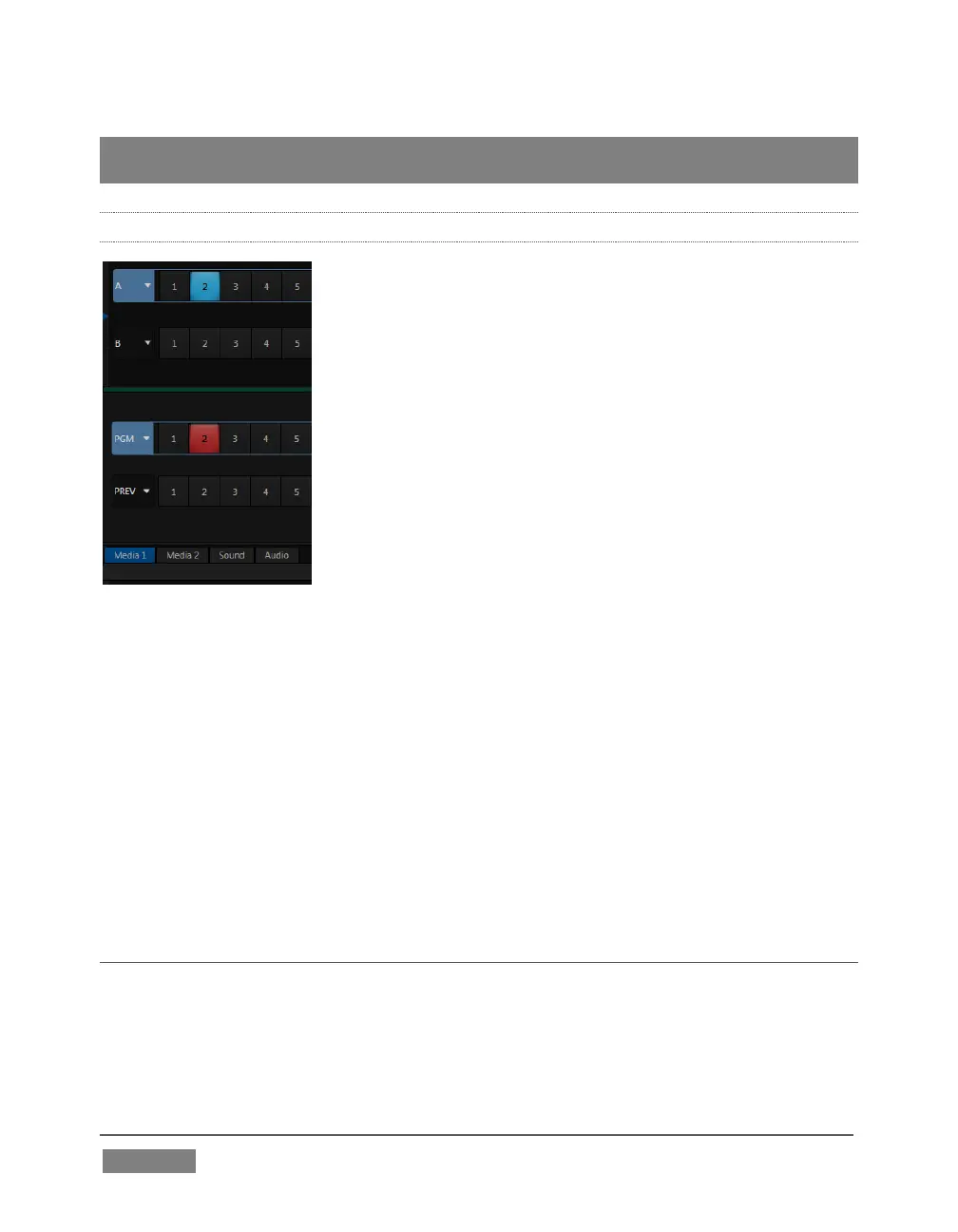
FIGURE 153
It can be very useful to link two (or more) Switcher or M/E source rows together,
causing them to operate synchronously. The Program and Preview rows, and the
source rows in M/E panes show a downward pointing triangle to the right of the row
label. Click it to open a menu that lets you set up linking.
As you’d expect, rows assigned to the same color groups are linked. A selection made
in any linked row updates the selection of all other rows in the same color group to
match. Thus Figure 153 shows the Input A row for an M/E linked to the PGM row of
the main Switcher. The “No Group” menu item removes the current row from a group,
while “Clear Group” removes all rows from the current group.
SECTION 9.3 TRANSITIONS
We discussed video layers in Section 9.2. With this in mind, it’s easy to comprehend
the layout and use of TriCaster’s Transition controls.