Page | 235
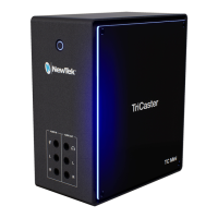
In either Mix or Effect mode you will observe two
source button rows at left labeled input A and B (Figure
222) by default.
At right are up to four Key control groups, depending
on which TriCaster model you are using. In most
respects these are identical in appearance and practice
to the DSK controls located in the main Switcher (see
Section 9.3.1).
Even the central control group mimics the main Switcher, with its Transition
controls and options, T-bar and delegate buttons and so on.
14.2.1 MIX MODE
Really, an M/E in Mix mode is a switcher:
Input rows labeled A and B behave just like the main Switcher’s Program and
Preview rows
Transition controls work in the same manner
One or more Key channels stand-in for DSKs
M/E output can even be routed directly to one of TriCaster’s two main outputs
(as well as the IsoCorder section).
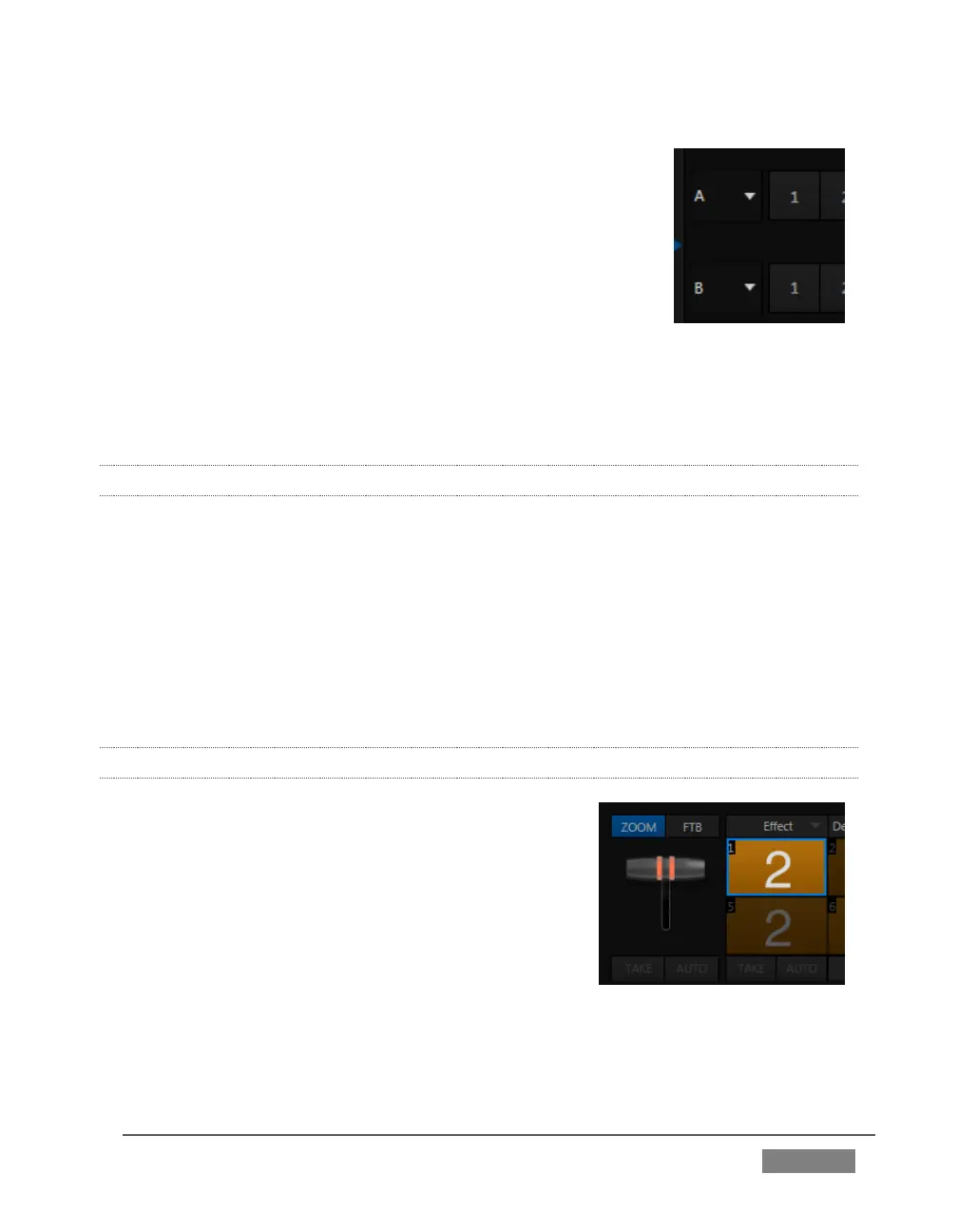
14.2.2 EFFECT MODE
Careful scrutiny reveals some (outwardly) subtle
differences in the controls when you change to Effect
mode (Figure 223):
The Take and Auto buttons normally located
beneath the T-bar and Transition icon are hidden.
A Zoom control button replaces the BKGD delegate.
The current Transition icon is replaced by the
default Effect icon.
FIGURE 223 (4-INPUT VERSION)