R&S
®
CMW 500 WiMAX Applications
WiMAX TX Measurements
Operating Manual 1202.3986.32 – 03 370
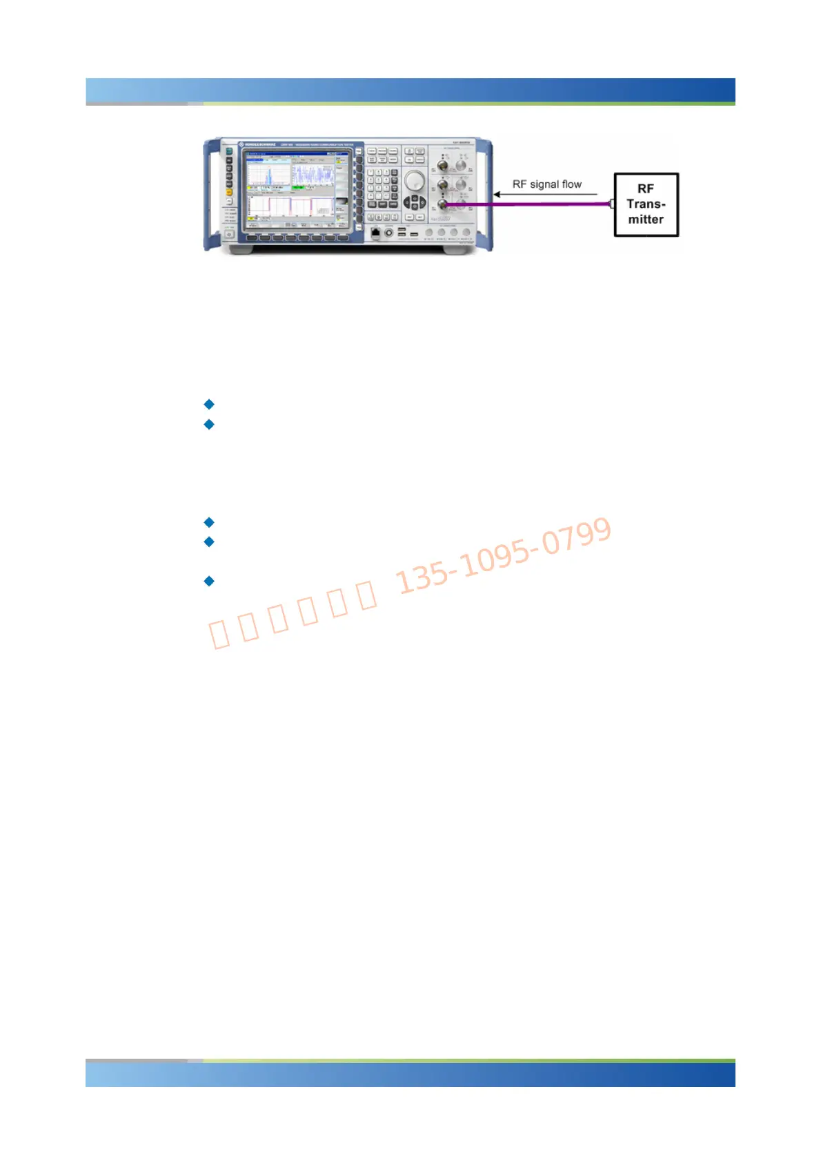
10.1.1.2 How to Measure an UL OFDMA Signal
After connecting your WiMAX subscriber station to the R&S CMW 500 as shown
above, you have to adjust the following analyzer settings to the properties of the
analyzed signal:
The analyzer "Frequency"
The "Expected Nominal Power" and (optional) a "User Margin" and "External
Attenuation".
For proper signal decoding, the settings in the "Measurement Parameters" section of
the configuration menu and its subsections must be compatible with the measured
signal. The settings are grouped as follows:
The "Measurement Parameters" specify the size of the uplink frame.
The "Zone Definition" parameters specify how sub-carriers are assigned to logical
sub-channels.
The "Map of Bursts" settings select the logical sub-channels and slots which
belong to the analyzed burst.
A power trigger synchronizes the measurement to the measured bursts.
10.1.1.3 Frame Settings and Burst Selection
An OFDMA uplink signal is a periodic sequence of UL frames; each of which can be
depicted as a rectangle in the frequency/time plane. The "Frame Length" (frame
duration) corresponds to the number of OFDMA symbols per frame times the symbol
duration. The covered frequency interval depends on the number of used subcarriers
and the subcarrier spacing f; it must not exceed the nominal bandwidth of the
OFDMA channel. Inverse Fast Fourier Transform creates the OFDMA waveform; the
"FFT Size" must be adjusted to the number of used subcarriers.

 Loading...


