Section 04 ENGINE (2-STROKE)
Subsection 02 (REMOVAL AND INSTALLATION)
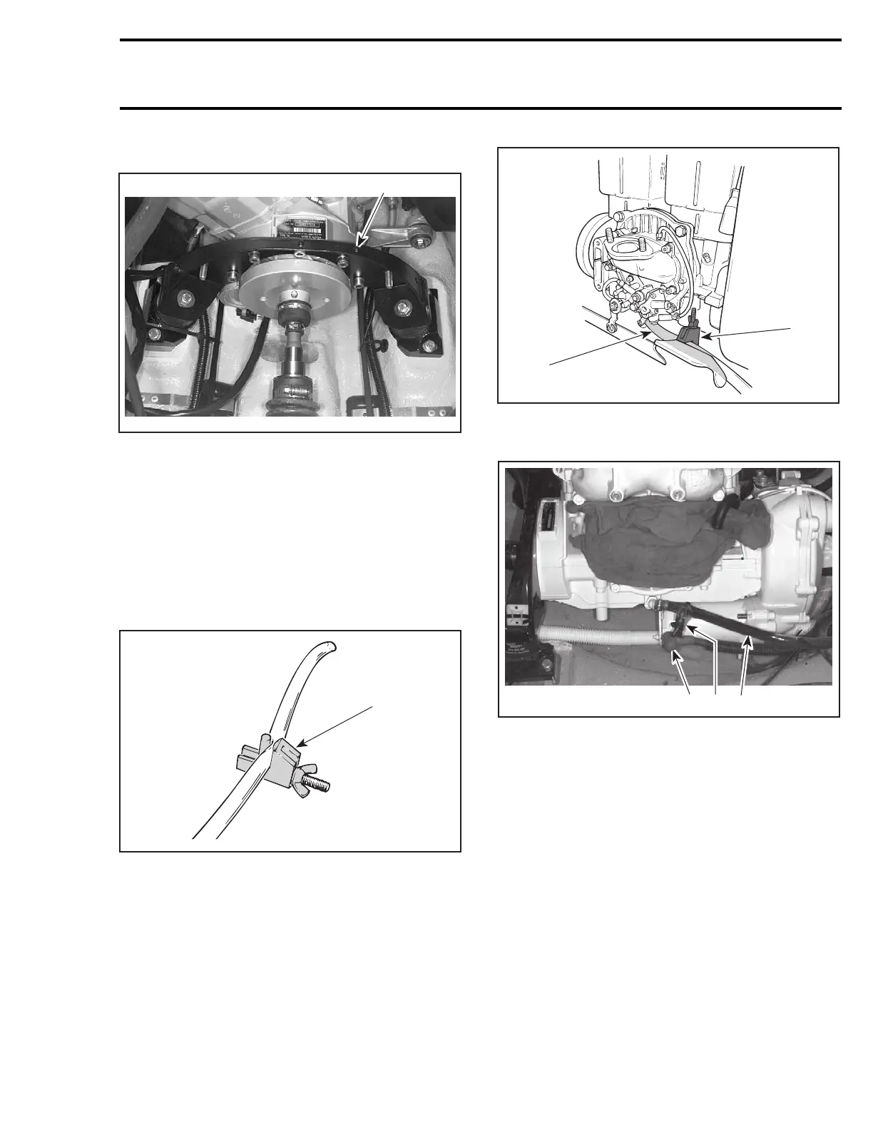
Remove rear engine support.
1
F07F12A
TYPICAL
1. Rear support
Removal of Remaining Components
Lift up engine slowly until oil injection hoses can
be reached.
All Engines
Install a hose pincher to oil supply hoses of oil
injection pump and rotary valve shaft (except the
947 DI engines); then, disconnect hoses.
A01B2JB
1
TYPICAL
1. Hose pincher (P/N 295 000 076)
Install a hose pincher to oil return hose of rotary
valve shaft (except the 947 DI engines); then, dis-
connect hose.
F01D3ZA
2
1
TYPICAL — 717 ENGINES
1. Rotary valve oil supply line
2. Hose pincher installed
F04D10A
3 2 1
TYPICAL — 787 RFI ENGINES
1. Rotary valve oil supply line
2. Hose pincher installed
3. Disconnect RED positive cable
smr2004-Complete Line Up 75

 Loading...


