Section 04 ENGINE (2-STROKE)
Subsection 02 (REMOVAL AND INSTALLATION)
XP DI Models
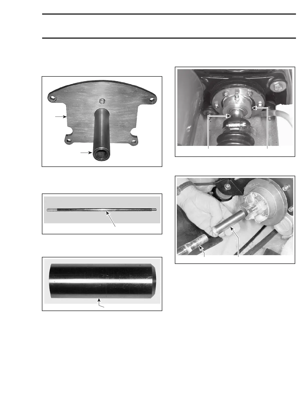
Use:
– plate (P/N 529 035 507)
F19J09A
1
2
1. Plate
2. Support
– alignment shaft (P/N 295 000 141)
F00B0GA
1
ALIGNMENT SHAFT
– PTO flywheel adapter (P/N 529 035 590).
F00B11B
1
1. Adapter
Install support plate at rear of watercraft.
Install adapter on shaft.
NOTE: First ensure the mid bearing shaft support
has been properly aligned prior to performing en-
gine alignment. Refer to DRIVE SYSTEM. Then,
ensurethemidbearingisloosenedtochecken-
gine alignment.
Carefully slide alignment shaft (P/N 295 000 141)
through shaft support and seal carrier.
F05I08A
1 2
TYPICAL
1. Alignment tool
2. Seal carrier
1
F08I06A
2
1. Alignment shaft
2. Adapter
Continue to slide the alignment shaft forward and
install PTO adapter (P/N 529 035 590) on shaft
end.
If the alignment is incorrect loosen engine support
screws to enable to align PTO flywheel with shaft
end.
NOTE: Use shim(s) (P/N 270 000 024) or (P/N 270
000 025) as necessary between engine supports
and rubber mounts to correct alignment.
smr2004-Complete Line Up 79

 Loading...


