Section 04 ENGINE (2-STROKE)
Subsection 02 (REMOVAL AND INSTALLATION)
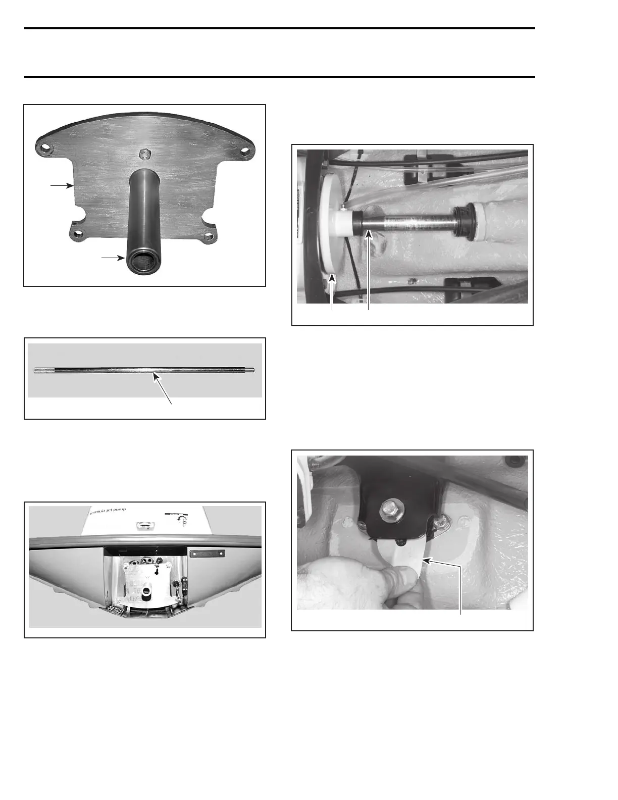
F19J09A
1
2
1. Plate
2. Support
Alignment shaft (P/N 295 000 141).
F00B0GA
1
1. Alignment shaft
All Models except XP DI
To verify alignment proceed as follows:
– Install the appropriate plate with the support to
hull with four nuts.
F00B0HA
– Carefully slide shaft through support.
– Insert shaft end into PTO flywheel.
NOTE: Ensure the protective hose and carbon ring
(or seal carrier) is removed to check engine align-
ment.
NOTE: If the alignment is correct, the shaft will
slide easily without any deflection in PTO fly-
wheel.
F07D05A
2 1
TYPICAL
1. Alignment shaft
2. PTO flywheel
If the alignment is incorrect loosen engine support
screws to enable to align PTO flywheel with shaft
end.
NOTE: Use shim(s) (P/N 270 000 024) or (P/N 270
000 025) as necessary between engine supports
and rubber mounts to correct alignment.
F00D0CA
1
TYPICAL
1. Shim
CAUTION: Whenever shims are used to cor-
rect alignment, never install more than 1.3 mm
(0.051 in) shim thickness on the 947 DI engines
and 3 mm (0.12 in) on the 717 and 787 engines.
78 smr2004-Complete Line Up
 Loading...


