Section 04 ENGINE (2-STROKE)
Subsection 03 (MAGNETO SYSTEM)
F06D0LA
1
TYPICAL
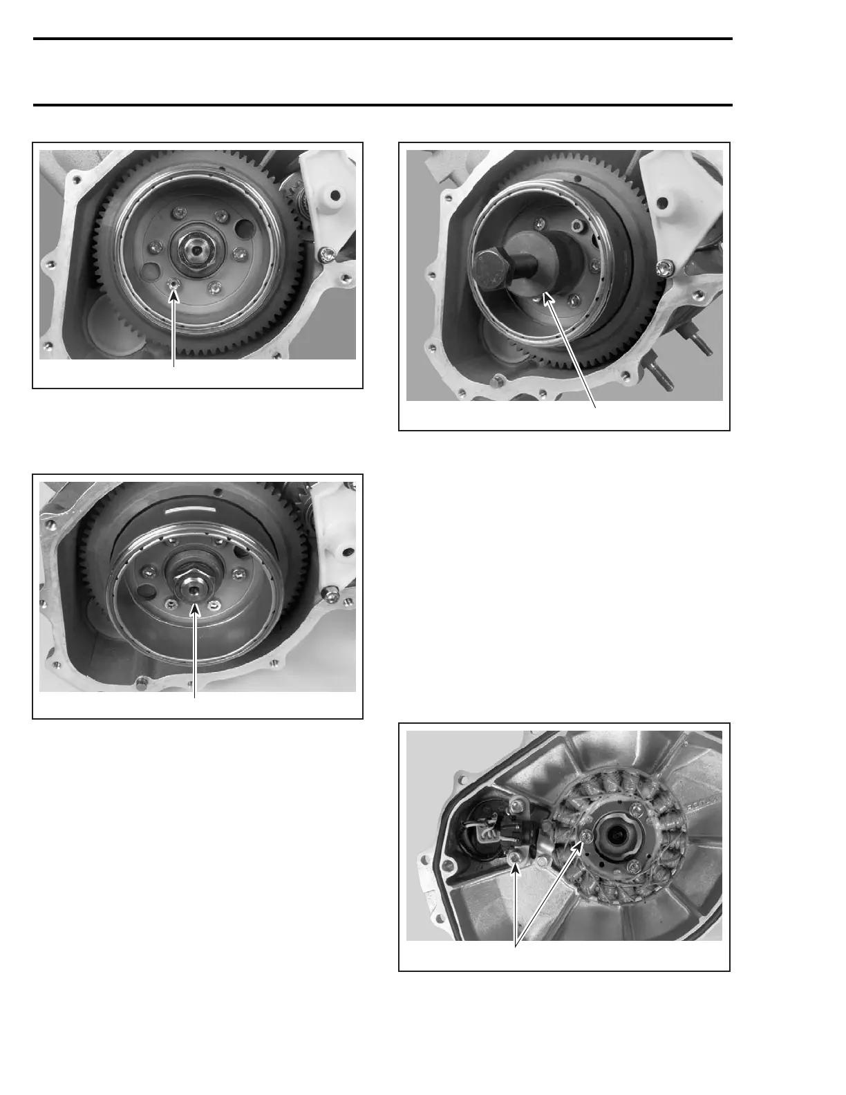
1. Screw
To remove the ring gear/rotor assembly, unscrew
nut no. 13 counterclockwise when facing it.
F06D0MA
1
TYPICAL
1. Nut
The magneto rotor is easily freed from crankshaft
with puller (P/N 420 976 235).
Install protective cap (P/N 290 877 414) to crank-
shaft.
Fully thread puller in magneto rotor.
CAUTION: Ensure to completely screw the
puller until it bottoms. Otherwise, not enough
threads would be engaged and damage may
occur.
F06D0PA
1
TYPICAL
1. Puller
Tighten puller screw and at the same time, tap on
screw head using a hammer to release magneto
rotor from its taper.
CAUTION: Be careful after ring gear removal
not to bend the encoder wheel teeth. Also pay
attention when putting away. If you suspect a
bent tooth, refer to ENGINE MANAGEMENT for
inspection procedure.
Stator and Trigger Coil/CPS
(Crankshaft Position Sensor)
Loosen screws no. 20 and no. 21 to remove the
stator no. 9 and trigger coil no. 10 from the engine
magneto cover.
F06D0NA
1
1. Remove screws
92 smr2004-Complete Line Up

 Loading...


