Section 04 ENGINE (2-STROKE)
Subsection 07 (EXHAUST SYSTEM)
F01D82A
3
1
7 6
4
8
2
5
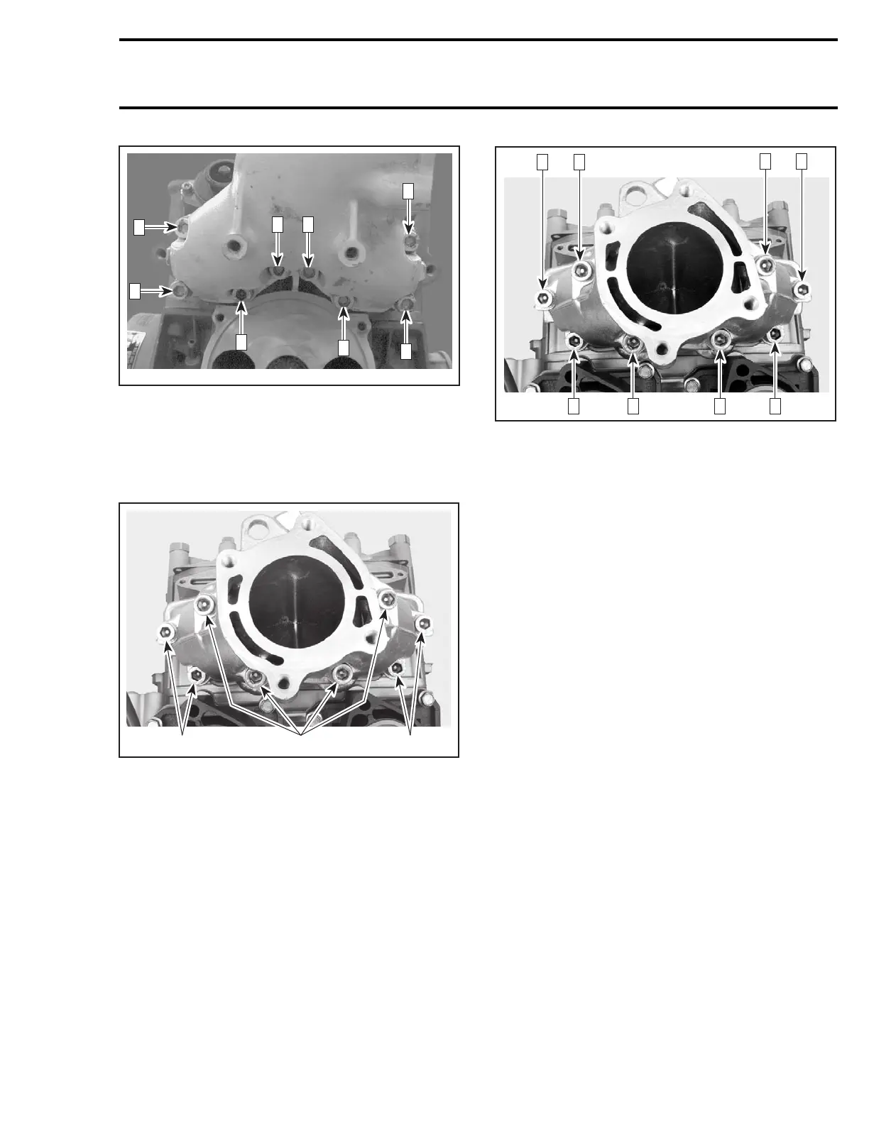
947 DI Engines
Apply Molykote 111 on threads of Allen screws
no. 12.
Install and hand tighten Allen screws no. 12 as per
following picture.
F06D1YA
1
2 1
1. M10x60Allenscrews
2. M10x110Allenscrews
Torque Allen screws to 24 N•m(17lbf•ft) as
per following illustrated sequence. Repeat the
procedure, retightening Allen screws to 40 N•m
(30 lbf•ft).
F06D1YB
7 4 1 5
8 2
3 6
Muffler
XP DI Models
At muffler reinstallation, ensure to properly posi-
tion fuel tank paddings so that fuel tank is centered
relatively to drive shaft. Secure straps.
Perform a fuel tank pressure test. Refer to FUEL
SYSTEM.
Tuned Pipe
717 Engines
CAUTION: Torque wrench tightening specifi-
cations must be strictly adhered to. Locking
devices (ex.: locking tabs, elastic stop nuts,
self-locking fasteners, etc.) must be installed
or replaced with new ones where specified. If
the efficiency of a locking device is impaired, it
must be renewed.
Ensure rubber bushings no. 19 and sleeve no. 18
are not damaged and are properly installed into
tune pipe support(s).
CAUTION: Damage to bushings and/or sleeve
will eventually cause stress to tuned pipe and
may cause cracking.
Make sure that gasket no. 16 is properly located
on exhaust manifold prior to finalizing pipe instal-
lation.
Apply Loctite 243 (blue) on nut no. 8 and screws
no. 6 and no. 12.
NOTE: Hand tighten all fasteners before torquing
any of them. For torquing sequence, see the fol-
lowing illustrations.
smr2004-Complete Line Up 175

 Loading...


